Requirements and Verification
This page describes requirements and how requirement verification is managed.
Note
The image for a requirement is a thought bubble.

Requirement icon
Requirements
Requirements are usually managed in official requirements management packages such as DOORs by IBM. In these packages strict procedures and business processes are embedded according to the needs of the organisation, and regulatory requirements. It is not the intention to replace these systems, but instead to keep the requirements stored in the systems as the source data, and add additional information to these references, information such as models that satisfy them, studies that meet them etc.
However in order to use the requirements in a collaborative environment, sufficient of the source information needs to be available for dissemination. Therefore the requirements have a textual definition, and optional associated documents and properties. For more information see SysML - Requirements Diagram.
Relationships between requirements
When it is necessary to relate requirements to other requirements, three types of relationship are provided:
- Contradiction
- Tracing (e.g. Ability to land at small airports to the requirement for a maximum wing span)
- Decomposition (e.g. MaximumAircraftWeight is decomposed to MaxFuselageWeight, MaxWingWeight etc)
These relationships can be further classified if needed.
Note
The icon for a requirement relationship is the requirement icon with a double ended arrow

RequirementRelationship icon
Relationships and Studies
Requirements can be identified as an “objective” for a study (see also Study Management). This leads to verification as described later on this page.
New requirements can be identified as a result of work that has been carried out as part of a study. When this happens the study is identified as the source for the new requirement.
Worked example using Business Object Model Classes
In the example, a first study is carried out to compute a deflection. This proves satisfactory, but with insufficient accuracy. A second study is carried out, with the same requirement for maximum deflection, but with an additional objective for greater accuracy. During the work of this study it was found that the results are very dependent on the material properties, and so a new requirement is added to constrain the variability of the material properties. This new requirement has its source as the second study, and is traced to the objective for that study.
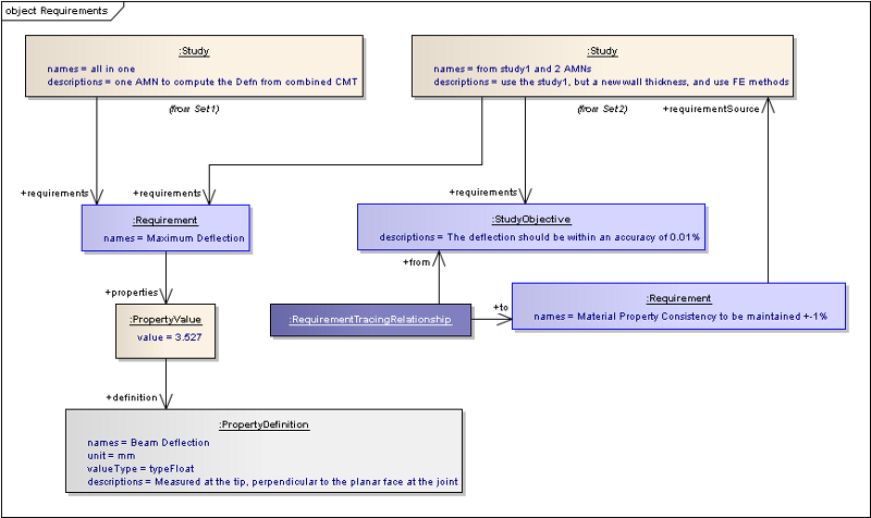
Study objectives as requirements
The elements of the two Associative model networks for this scenario are shown below.
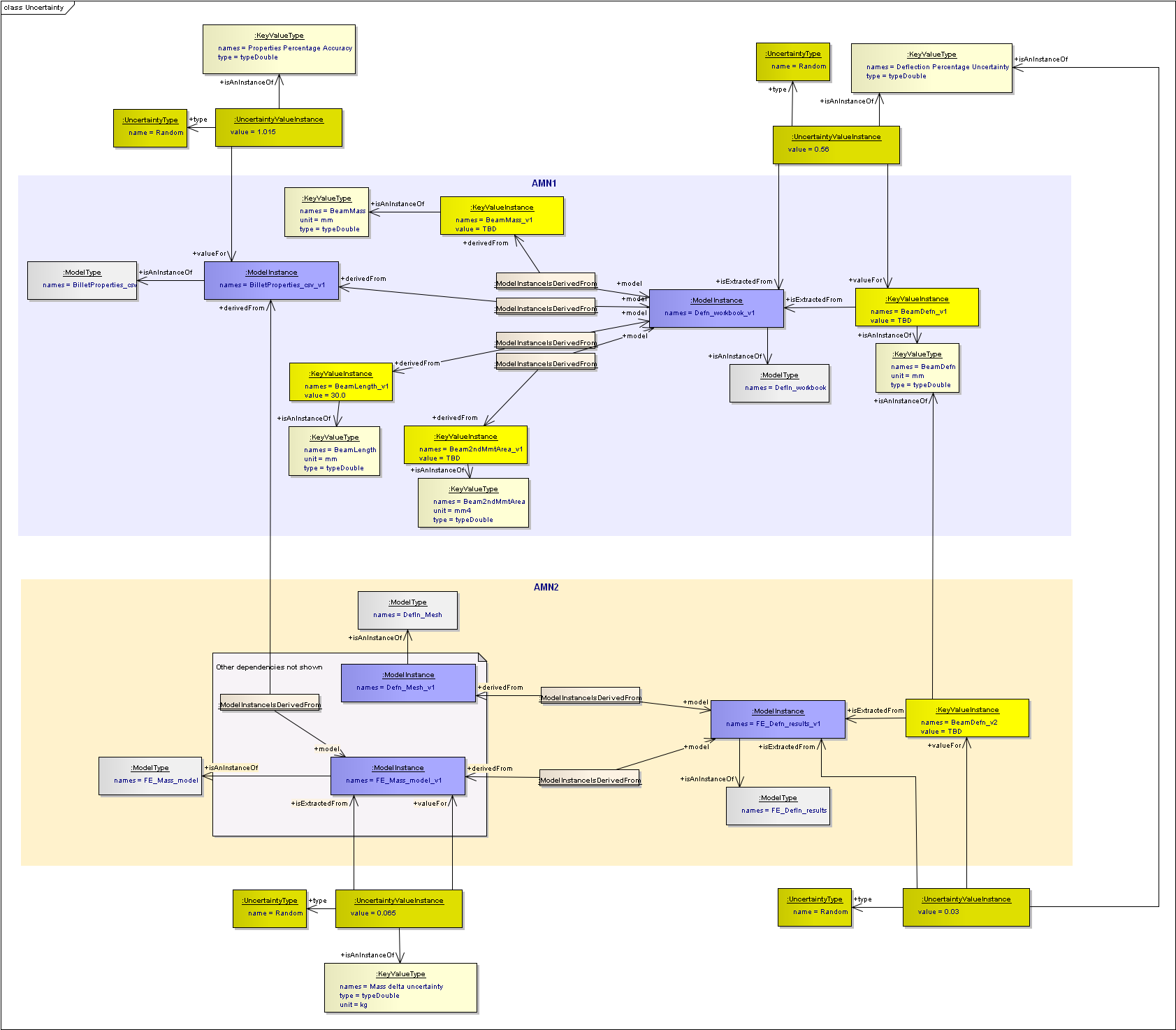
Two AMNs with uncertainty values
For more details and the background on this example, see: Introduction to the Very Simple Example.
Enterprise Architect Documentation
For more information see SysML - Requirements Diagram
Links to Value Modelling
Value modelling has specialisations of requirement objects that add stakeholders and focal points. These specialisations are for StakeholderExpectations (expressed and validated) and for StakeholderNeeds. The Expectations are captured as part of an ExpectationCaptureStudy, and become the source for the Needs as part of a NeedsAnalysisStudy. At this point, Value Dimensions are associated to the needs. See SysML - Need Analysis Study for more details.
The Needs are then input into a ValueCreationStrategies [VCS], which itself is a specialisation of a study. The specialisations are to be able to rank or weight the input StakeholderNeeds within the context of that VCS, and to assign Value Drivers to those Needs. Then QuantifiedObjectives and Targets are identified to fulfil the StakeholderNeeds again in the context of that strategy. See SysML - Value Creation Strategy for more details.
Verification of Requirements
There are two parts to the verification of requirements:
Identification of the item that the requirement should be satisfied by

Requirement Should-Be-Satisfied-By icon
Identification of the evidence that will show (or has shown) that it has satisfied the requirement

Requirement Verification icon
For example there could be a requirement that all items in the equipment bay must not exceed a surface temperature of x degrees. So the item(s) that are going to satisfy the requirements are all the items in the equipment bay, and each one will provide a thermal analysis as the evidence that it has/has not satisfied the requirement.
In the planning phase these can be identified even though the work has not been done. So it is possible to declare up front how a requirement is to be verified, and so this information can be used in planning. At this point the status of the verification is “To_be_verified”. When the work is underway the status is set to “In_work”. On completion of the work, the status is updated to indicate how well it has been verified (e.g. Qualitative, Quantitative etc). Note: the values for the status given here are for illustration only. The actual values are determined by business rules.
Depending on the requirement, different types of object can be used to satisfy it, e.g.
- Requirement that all items in the equipment bay must not exceed a surface temperature of x degrees
- Satisfied by: Components (or their representative model instances) in the equipment bay.
- Supporting Verification Evidence: Thermal Analysis model instances for all components in the equipment bay
- Requirement that virtual test data is within tolerance of actual test data.
- Satisfied by: Method.
- Supporting Verification Evidence: the comparison of the virtual to actual test data. This could be a ModelInstance or a QualityReportInstance. It could also be a KeyValueInstance of the tolerance which is extracted from the comparison ModelInstance/ QualityReportInstance.
- Requirement that the results of an analysis are accurate within a particular level of uncertainty
- Satisfied by: Model Instance.
- Supporting Verification Evidence: an uncertainty value instance for the ModelInstance (that was computed using various inputs such as the uncertainty of the analysis inputs, the predicted accuracy of the analysis method etc).
- Requirement that a wing has a weight less than x kg
- Satisfied by: (Wing) Component.
- Supporting Verification Evidence: a Key Value instance that was extracted from a mass model that is a representation of the wing component.
- Requirement that the conduction between the nacelle and engine does not exceed x
- Satisfied by: Interface Connection.
- Supporting Verification Evidence: the model instance that is the analysis of the conduction between the engine and nacelle, this is most likely also a representation of the interface connection
- Requirement that the joint between a wing spar and cover does not suffer from bolt pull through.
- Satisfied by: Interface Port (on the wing spar component and wing cover component).
- Supporting Verification Evidence: the bolt pull through reserve factor key value instances extracted from the model instance that is the analysis of the bolt pull through.
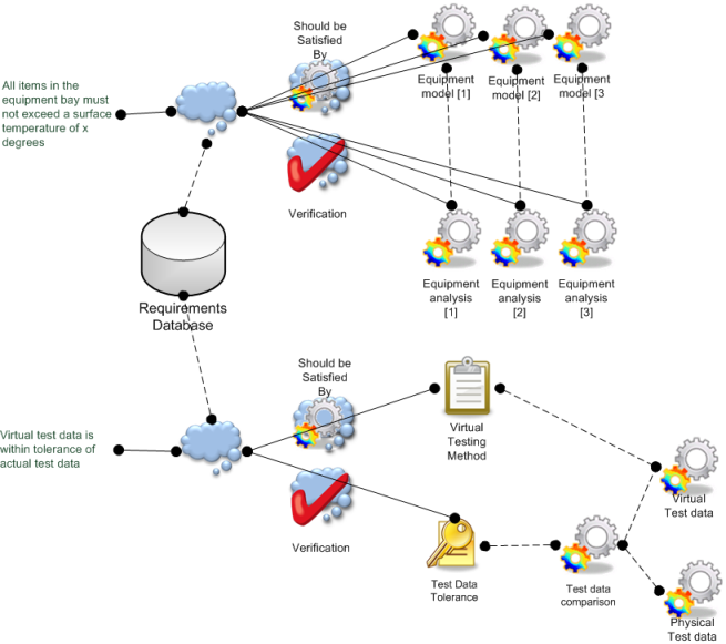
Illustration of the first two of the above Requirement Verification examples
Enterprise Architect Documentation
For more information see SysML - Requirement Verification Diagram
Worked example using Business Object Model Classes
Continuing the Business Object Model worked example above that showed the requirements associated to two sequential studies, and also the Associative Model Networks for those studies. Now those requirements are associated to models in those networks to show that it is the BeamShellSolid ModelInstances that must satisfy the requirement for deflection, and the evidence used to verify satisfaction of this requirement are the BeamDeflection KeyValueInstances. Similarly the accuracy requirement must be satisfied by the BeamDeflection KeyValueInstance, and the verification evidence is to be provided by the deflection analysis results and the uncertainty value that is extracted from them. This is illustrated below.
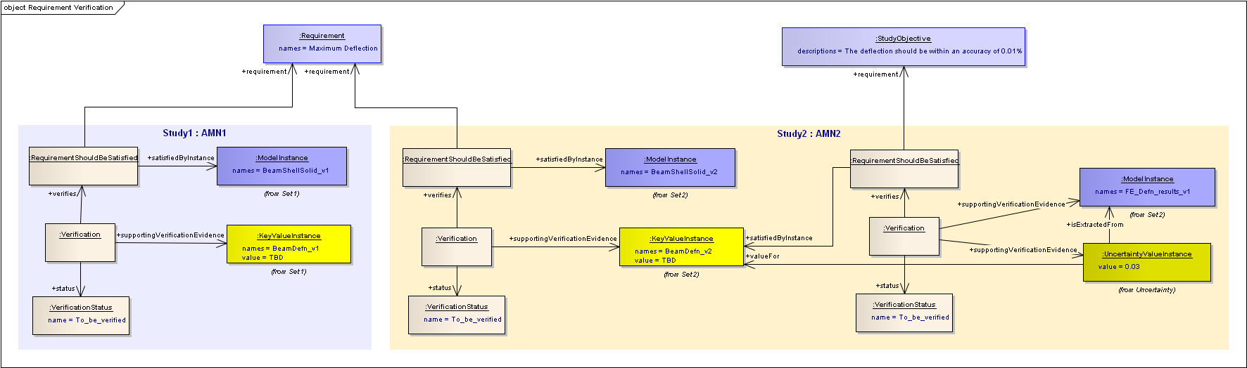
For more details and the background on this example, see: Introduction to the Very Simple Example.
Section author: Judith Crockford