The Very Simple Example
The name “very simple” is rather misleading. The problem is very simple, but the example has been expanded to illustrate many of the core features of the Business Object Model
Scenario Overview
The scenario is illustrated below.
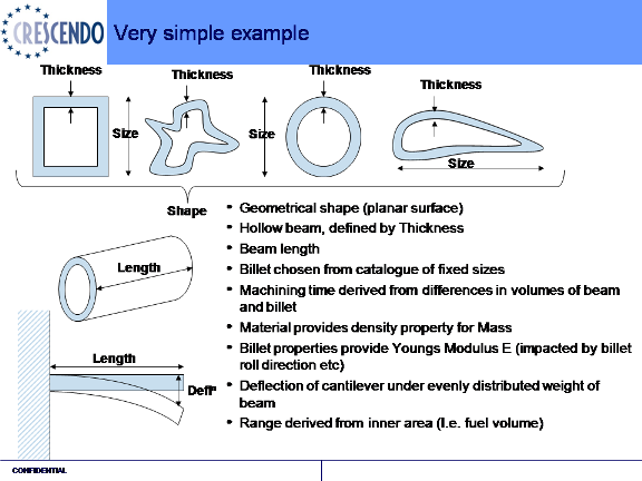
Very Simple Example
The aim is to compute the deflection of a beam.
The key features are:
- Geometrical shape (planar surface)
- Hollow beam, defined by Thickness
- Beam length
- Billet chosen from catalogue of fixed sizes
- Machining time derived from differences in volumes of beam and billet
- Material provides density property for Mass
- Billet properties provide Youngs Modulus E (impacted by billet roll direction etc)
- Deflection of cantilever under evenly distributed weight of beam
- Range derived from inner area (I.e. fuel volume)
The Associative Model Networks [AMN]
The following are illustrations of the networks for the example
Beam Geometry AMN
The first stage is to create the geometry for the example. It is may appear to be overly complex for the simple problem, but this is to enable illustrations of other areas. The first image shows the network and the
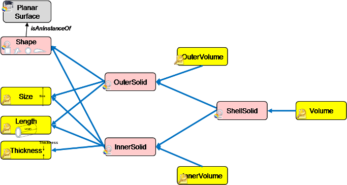
AMn for the Geometry (ShellSolid)
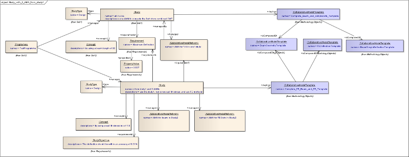
Representation using Business Object Model classes
This shows a study with a concept that is managing the AMN. The ModelInstances and KeyValueInstance belong to the AMN. The AMN is actually a combination of the Geometry and the Spreadsheet deflection.
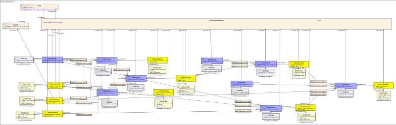
Associative Model Network for the Beam Geometry
The instances in the above diagram each have a corresponding type. The types are themselves in a Collaborative Model Template [CMT] which is shown in the second image.
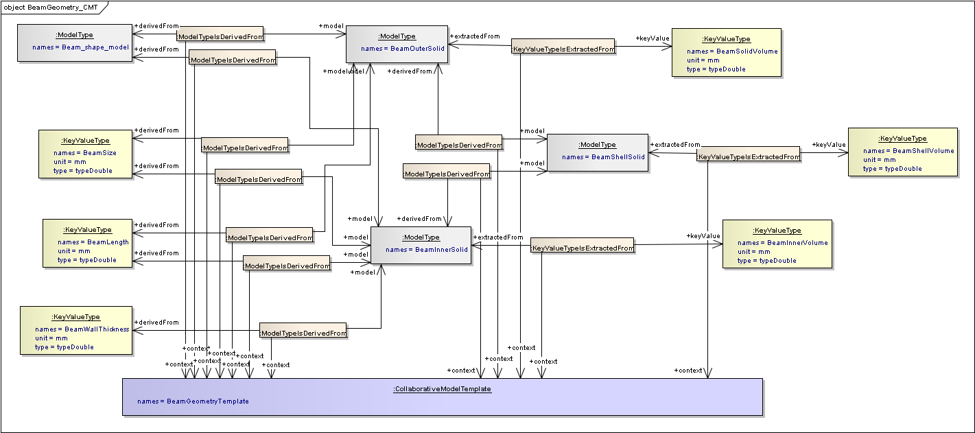
Collaborative Model Template for the Beam Geometry
Note
There are classes between the instances and types rather than direct relationships. This is because the link between needs to be referenced when the data flows are identified, therefore the link cannot be a simple relationship and must be a class.
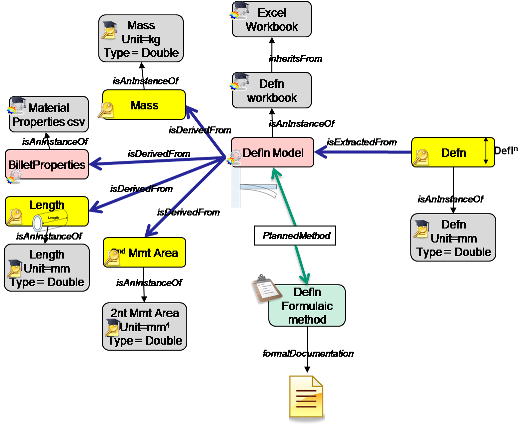
Deflection AMN
There are then two alternative ways to compute the deflection. The first is using a simple formula in a spreadsheet. This has several assumptions, or limitations, in that it is only applicable for prismatic shapes. The second approach is by using an Finite Element analysis. This can work on any solid shape, and it is probably over-kill for this example so can be used to illustrate a poor “utility” rating.
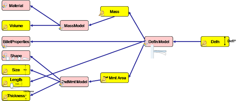
AMN for Deflection computed using a formula in a spreadsheet
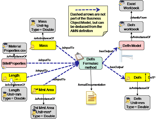
Representation using Business Object Model classes
This shows a study with a concept that is managing the AMN. The ModelInstances and KeyValueInstance belong to the AMN. The AMN is actually a combination of the Geometry and the Spreadsheet deflection.
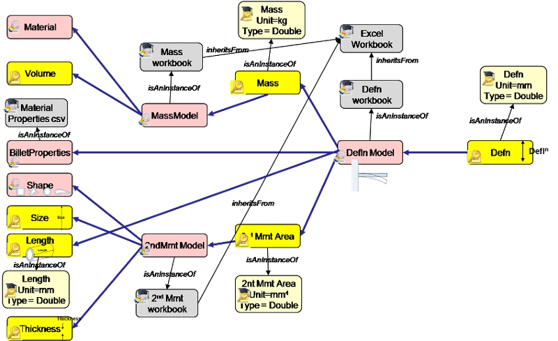
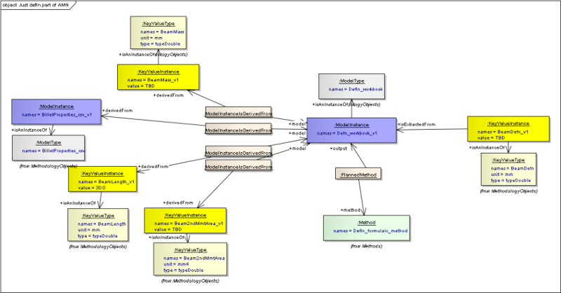
The schematic illustration of the deflection network but also including the types
Associative Model Network for the Beam Geometry
The instances in the above diagram each has a corresponding type. The types are themselves in a Collaborative Model Template [CMT] which is shown in the second image.
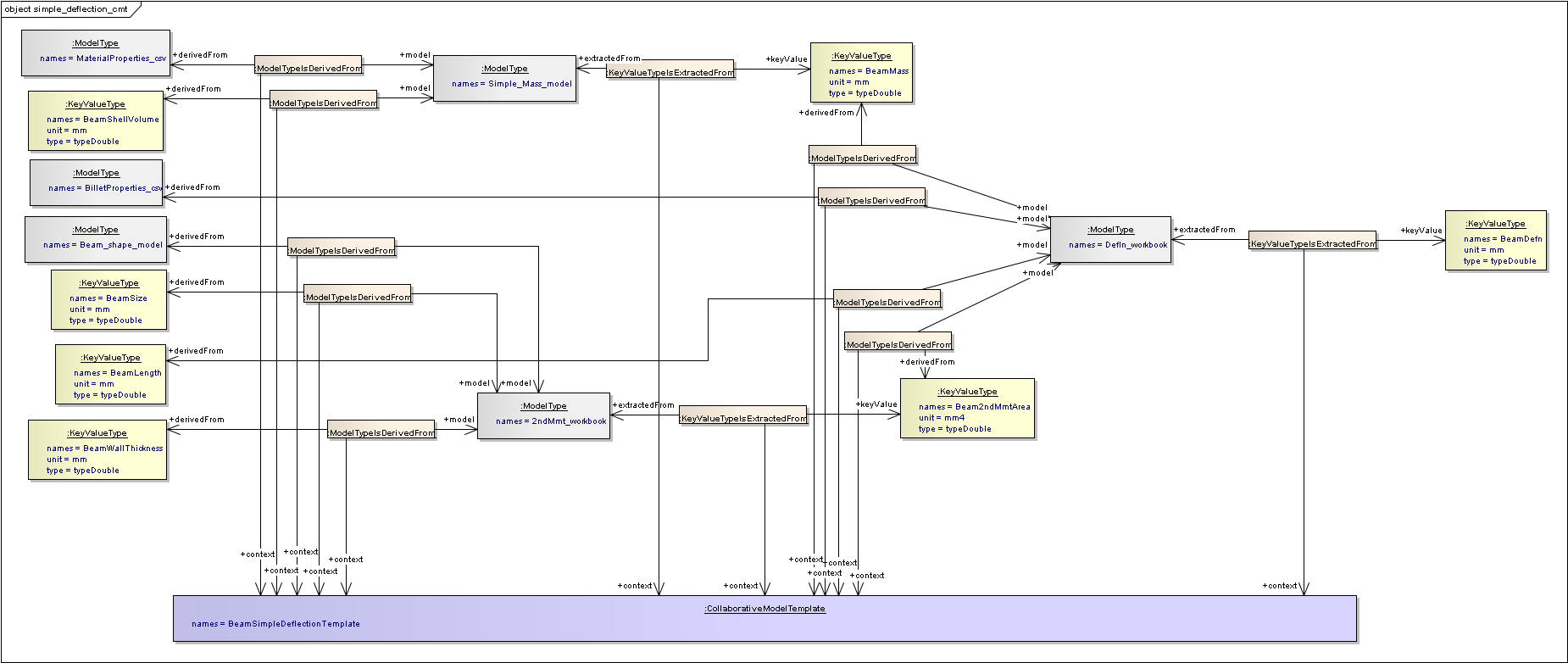
Collaborative Model Template for the Deflection computed using a formula in a spreadsheet
Note
There are classes between the instances and types rather than direct relationships. This is because the link between needs to be referenced when the data flows are identified, therefore the link cannot be a simple relationship and must be a class.
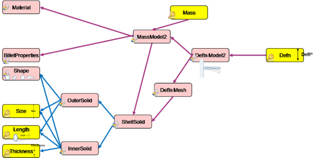
AMN for Deflection computed using Finite Element Analysis
Representation using Business Object Model classes
The example does not contain a single network that contains all the elements of the Finite Element Deflection analysis, because this is part of the second study which builds on the first study. Therefore only the Collaborative Model Template is shown here.
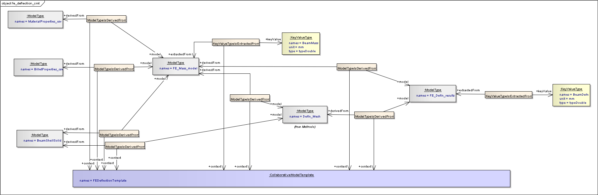
Collaborative Model Template for the Deflection computed using Finite Element Analysis
Note
There are classes between the instances and types rather than direct relationships. This is because the link between needs to be referenced when the data flows are identified, therefore the link cannot be a simple relationship and must be a class.
Manufacturing AMN
Finally there is a stage that brings in some manufacturing issues. Here the scenario is, that depending on the size of the beam, different billet sizes have to be used, and these have different material properties (Youngs modulus) due to the roll characteristics of the forging process
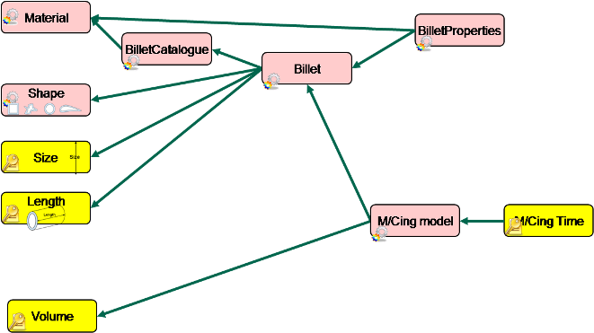
AMN for the manufacturing models
Combined AMN
These stages can be combined into a single picture, which are illustrated below using either the spreadsheet, or the Finite Element method of calculating the deflection.
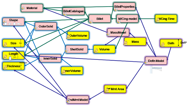
Combined AMN for the Geometry, manufacturing and spreadsheet deflection
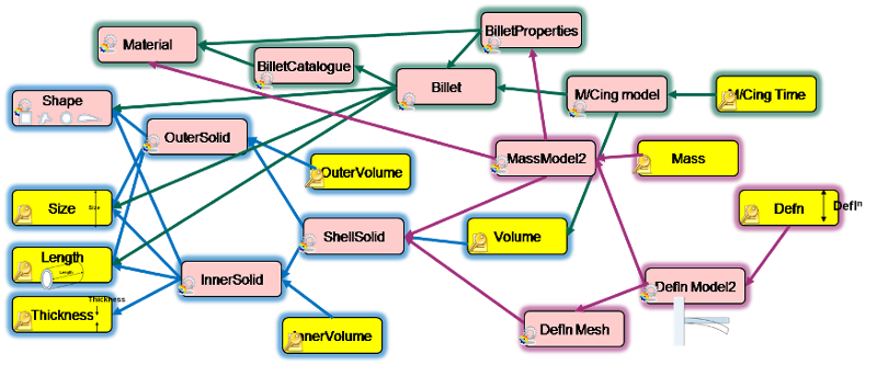
Combined AMN for the Geometry, manufacturing and FE deflection
Links and images used in other pages
Requirements and Verification
See Requirements and Verification
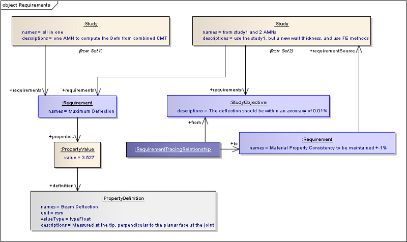
Study objectives as requirements
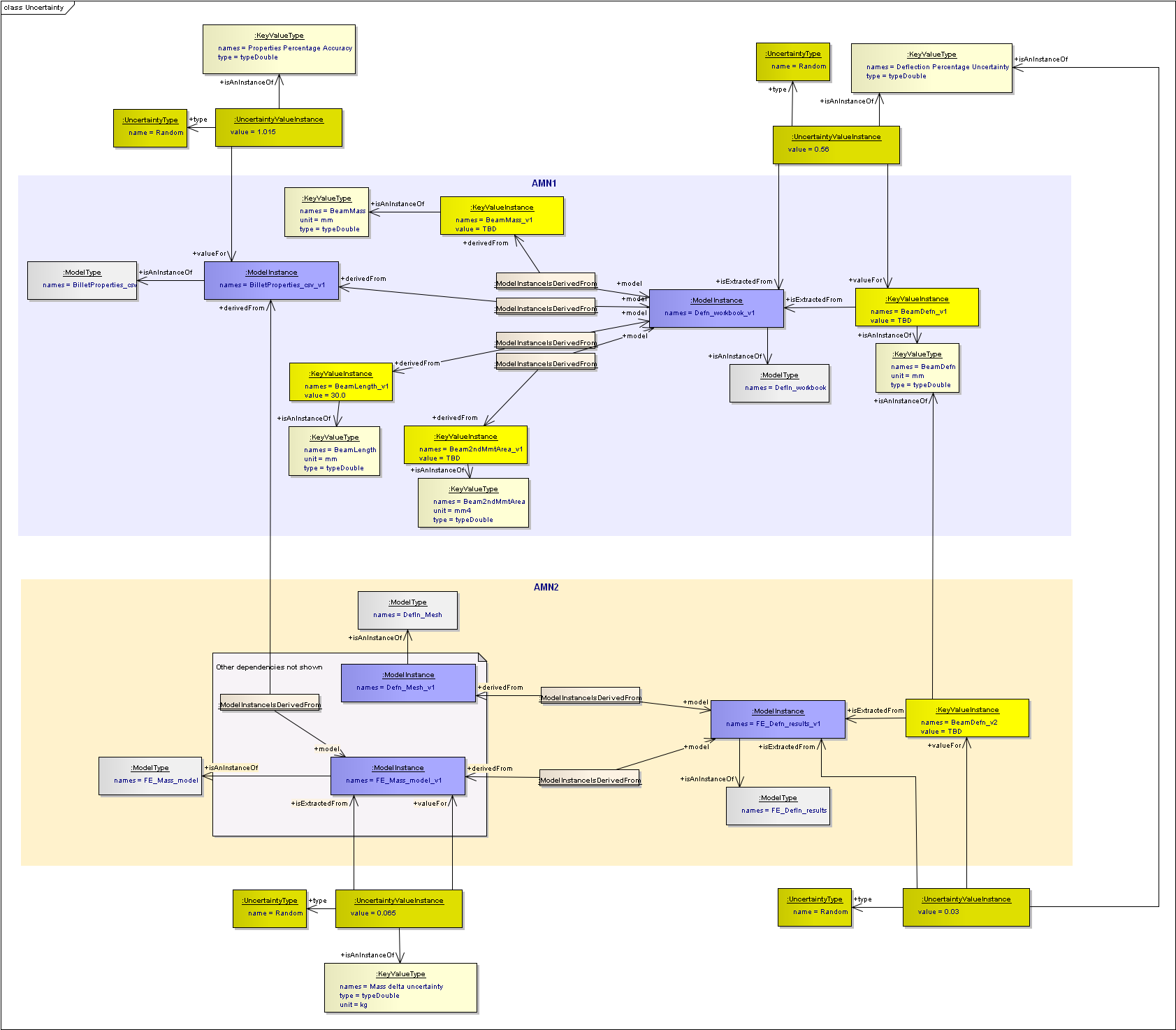
Two AMNs with uncertainty values
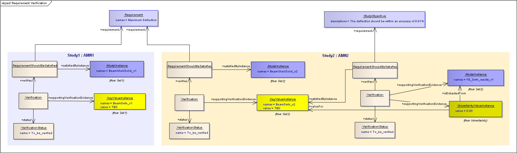
Requirement Verification
AssociativeModelNetwork and workflow
See AssociativeModelNetwork and workflow
Part of an AMN surrounding a single element
Workflow view for the same element
Part of an Associative Model Network concerned with on model
Data flow view for the same model
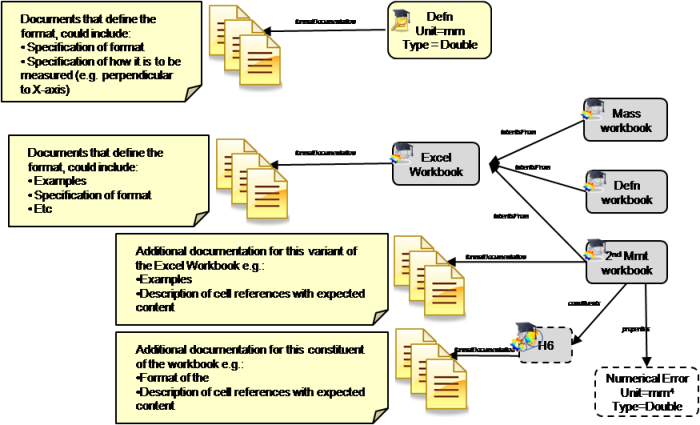
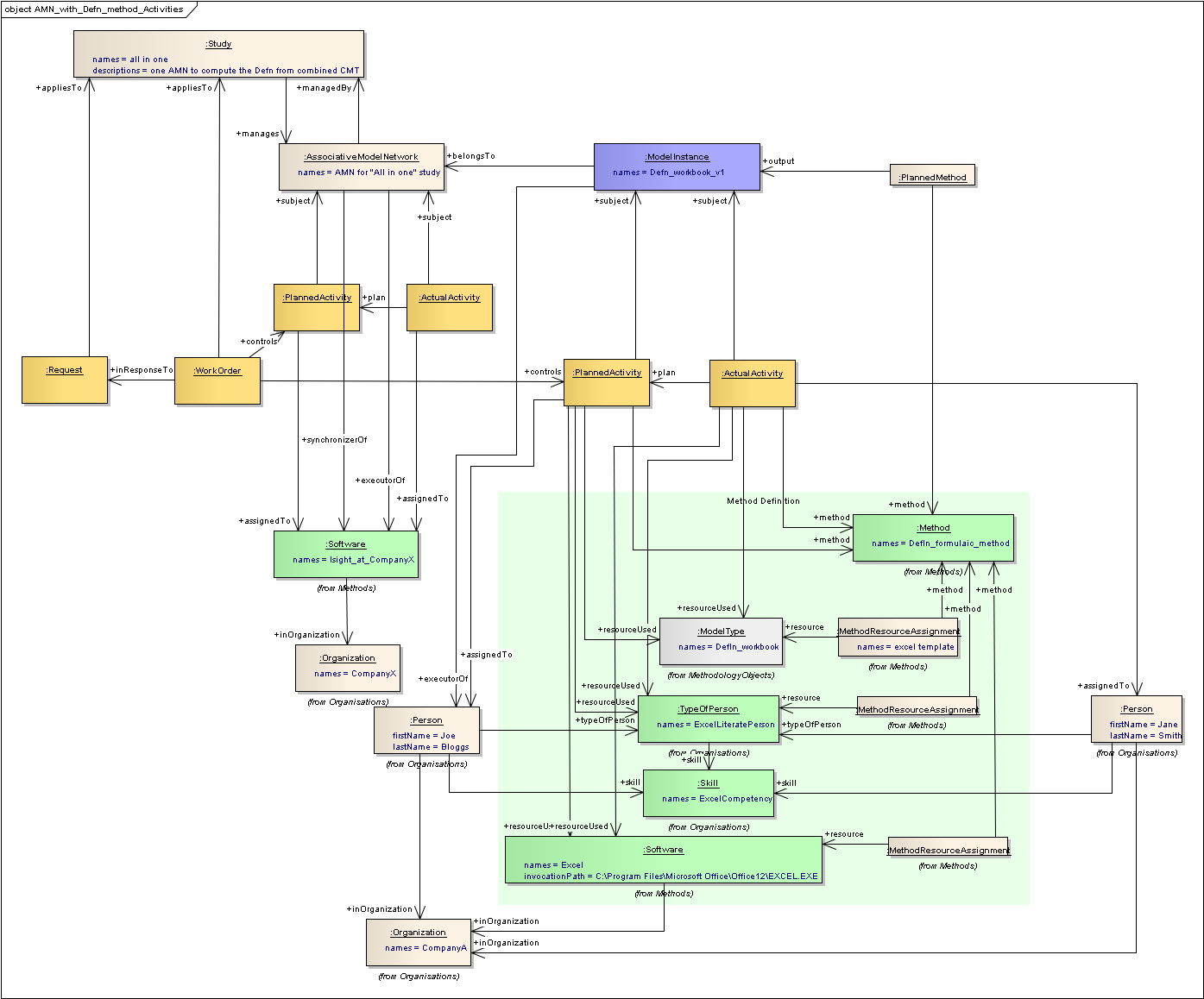
Method Definition
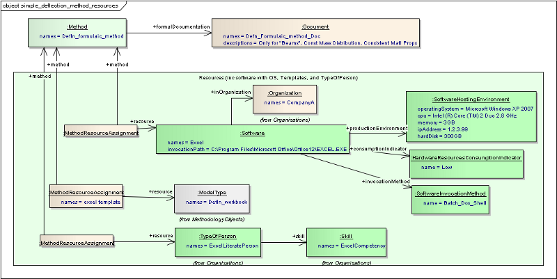
Named resources for a method
Equivalent using Business Object Classes
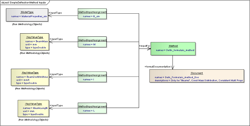
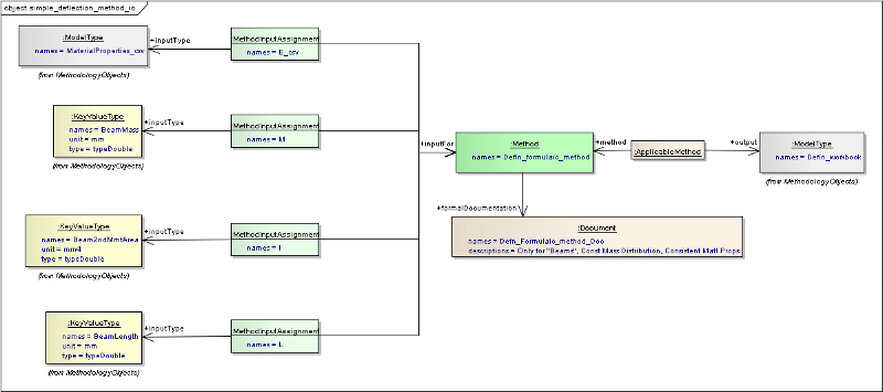
Method inputs with names
Different sets of inputs for a method
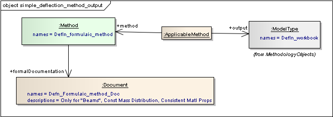
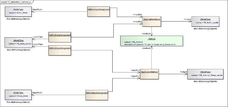
Method output (method is ‘applicable’ for Model type)
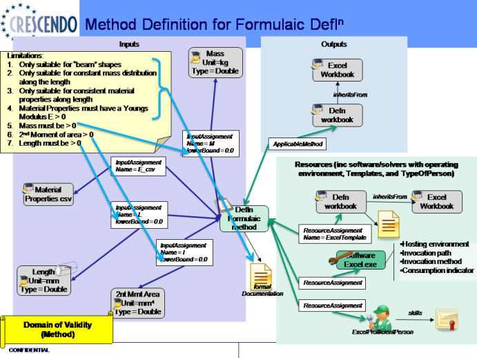
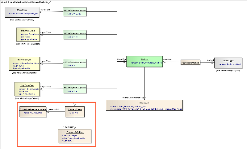
Limitations on inputs
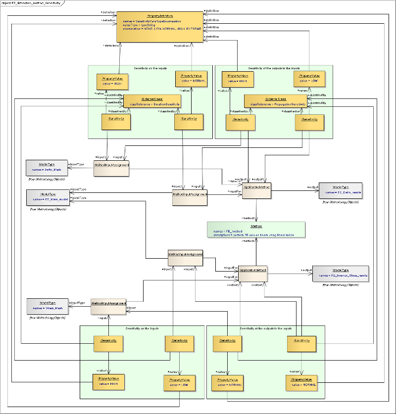
Duration and Propagation sensitivities on inputs and outputs
Methods DataFlow
See Methods DataFlow
BeamDefn using simple models and methods
BeamDefn using FE based models and methods
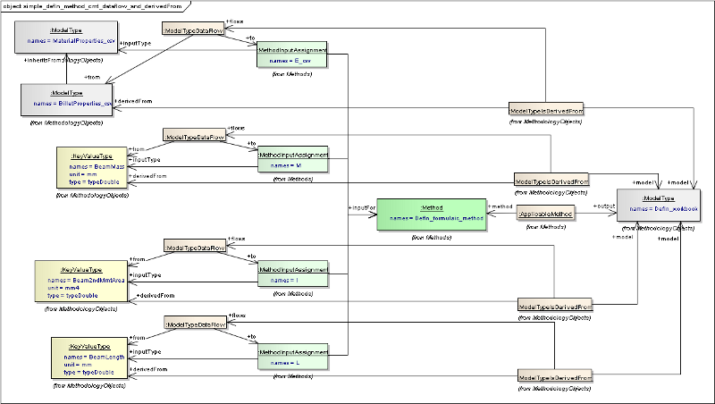
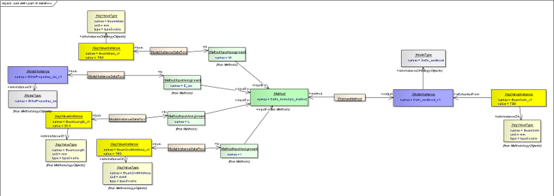
DataFlows connecting elements in the CMT
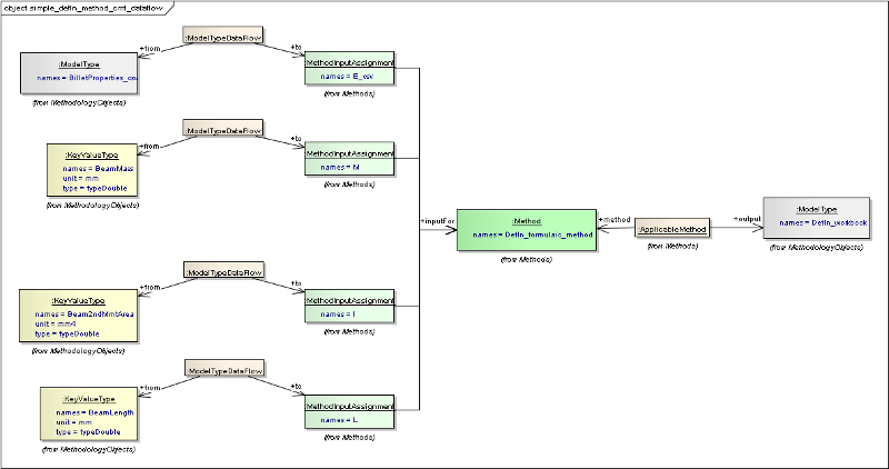
Showing just the elements that show the flow of data through the method
AMN to create the Deflection using the formulaic method
Area of the AMN relating to the Beam Deflection
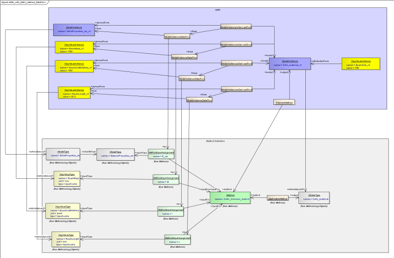
DataFlows connecting elements in the AMN to the method inputs
Showing just the elements that show the flow of data through the method
Quality Gates
See Quality Gates
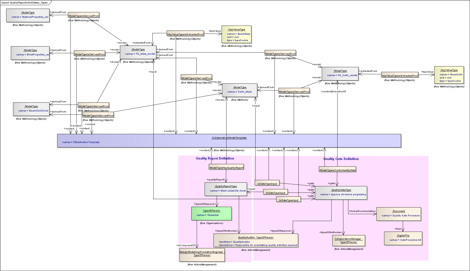
View of classes associated with a Quality Gate Type
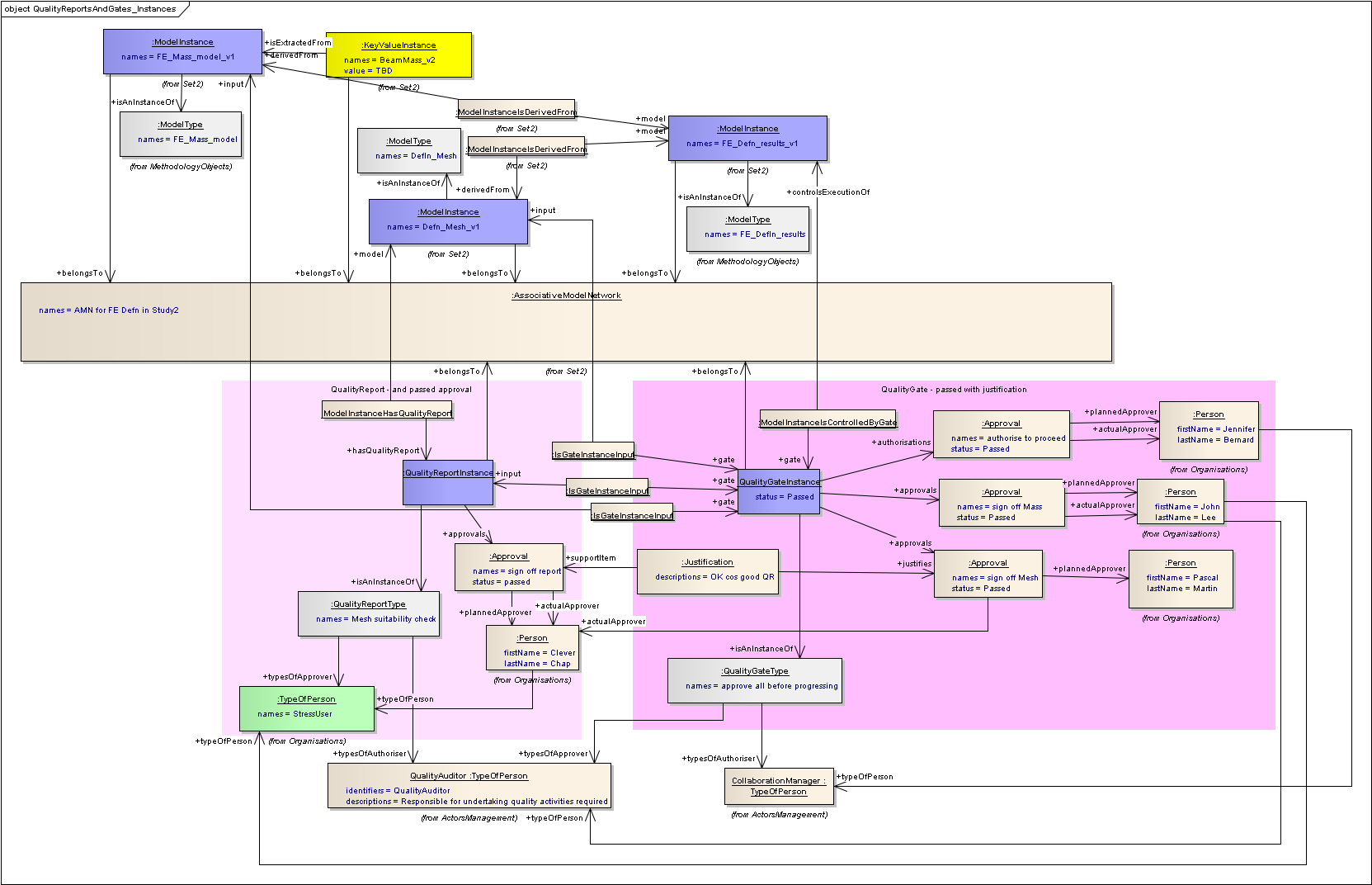
View of classes associated with a Quality Gate Instance
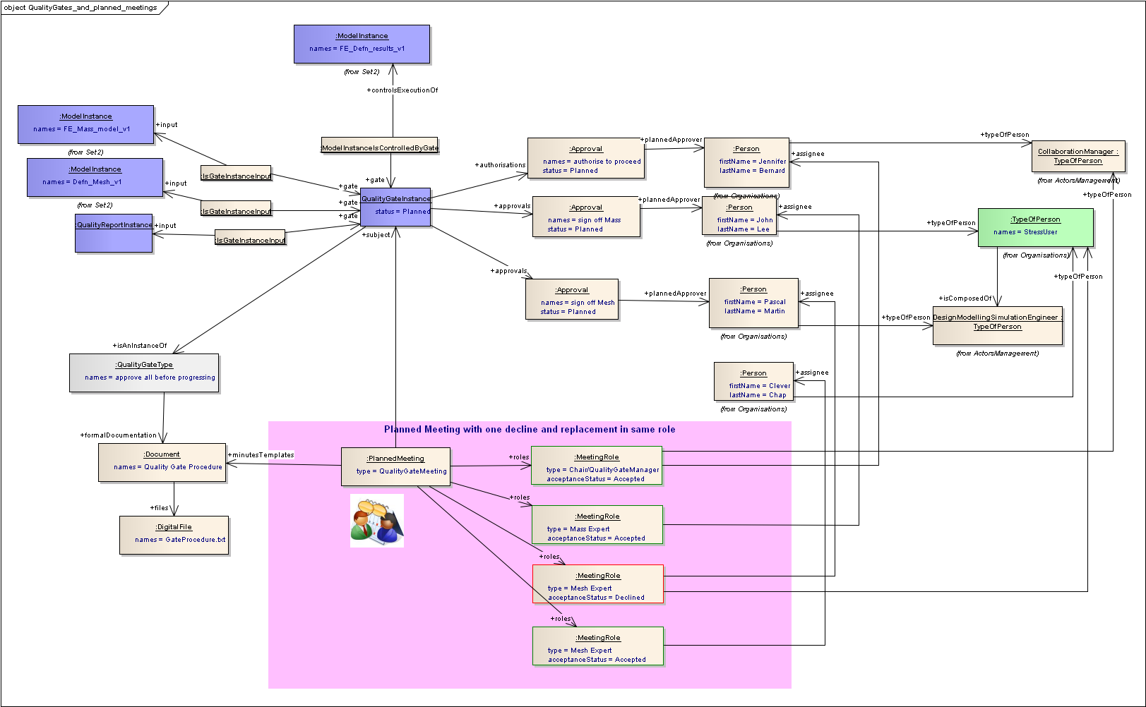
View of classes for a planned meeting for a Quality Gate
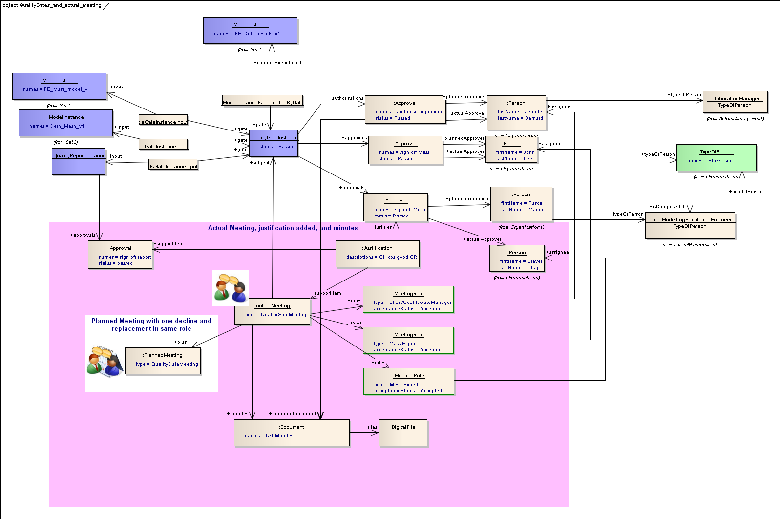
View of classes for a actual meeting for a Quality Gate
Templates and Instances
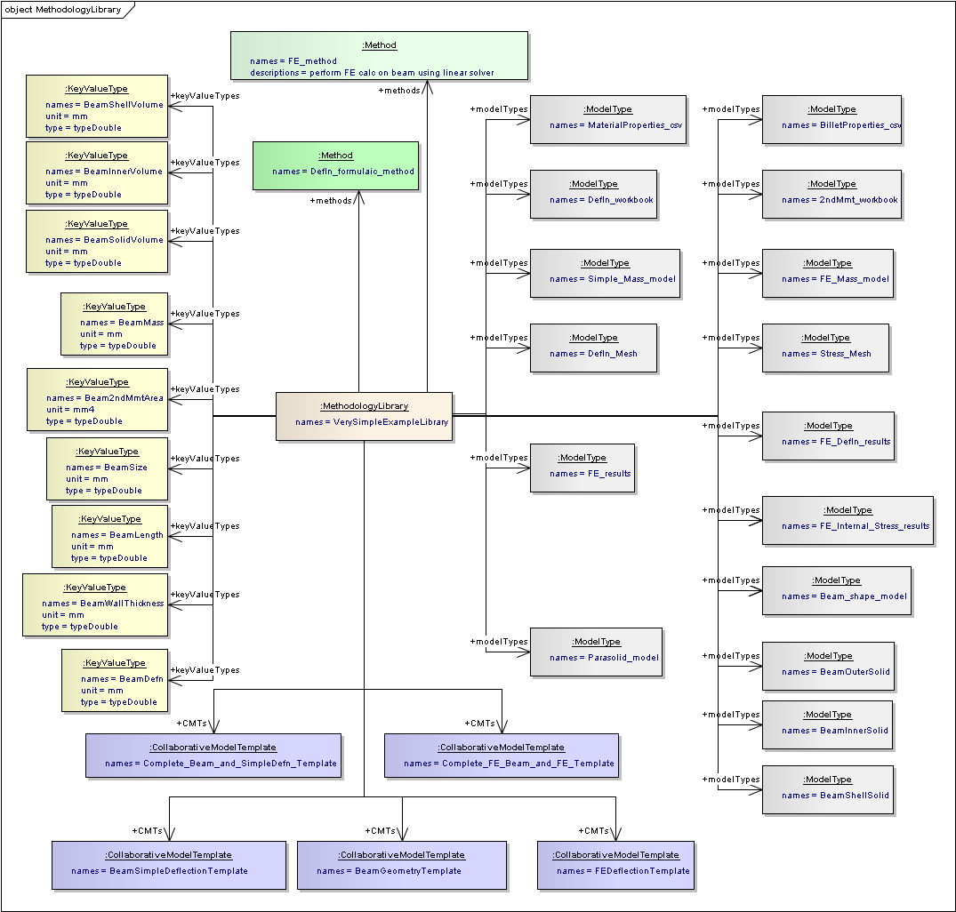
Methodology Library of VerySimpleExample in EA
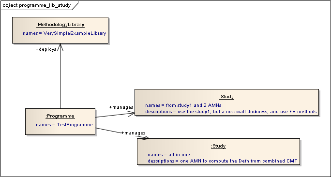
Programme that deploys a Methodology Library, and manages Studies
Documentation for the definition of Model Types and Key Value Types, including inheritance
Collaborative Process Management
See Collaborative Process Management
Process Management for Study, Associative Model network and Model Instance
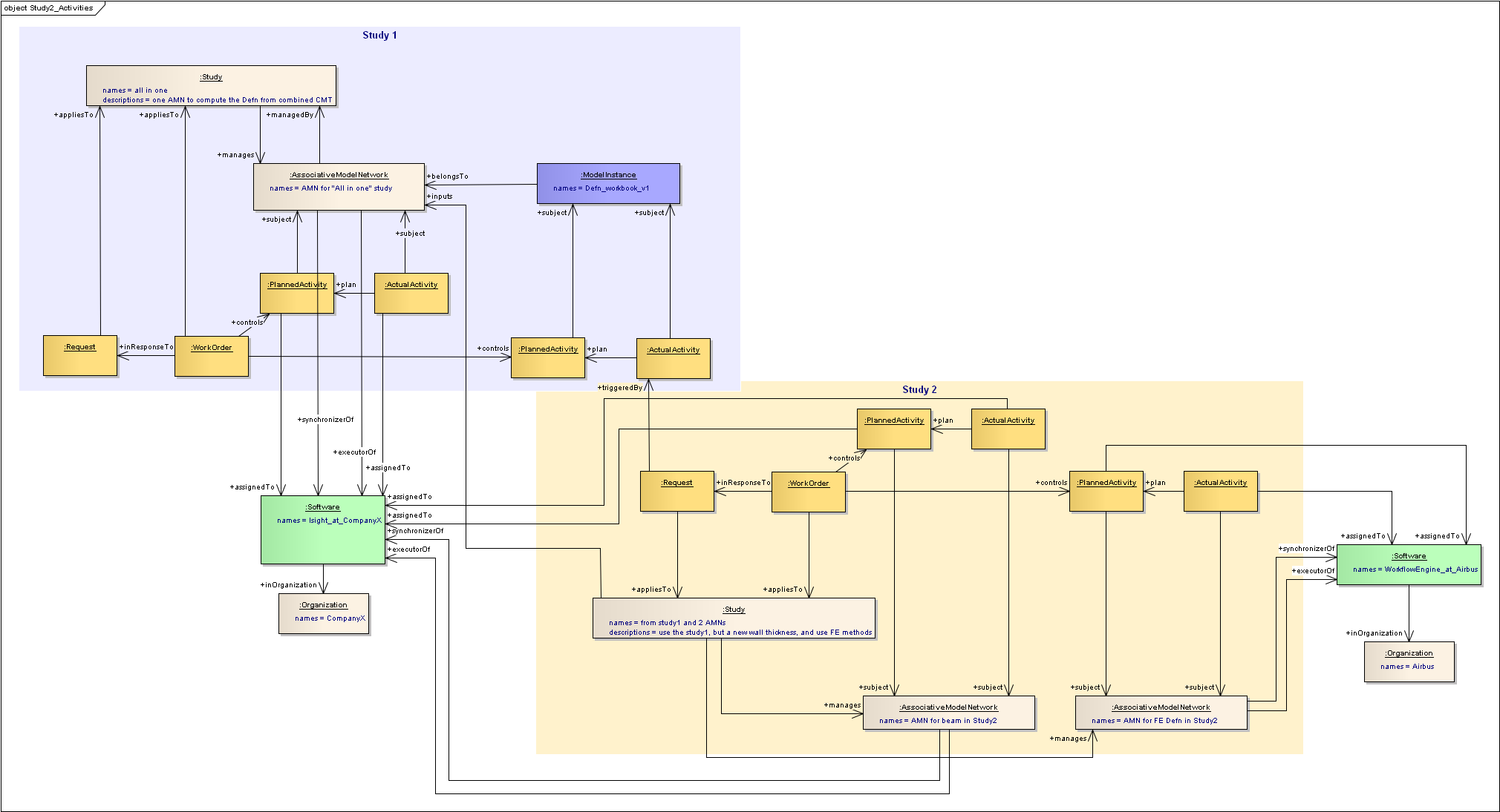
Series of Process Management objects with triggers
Security and Trust
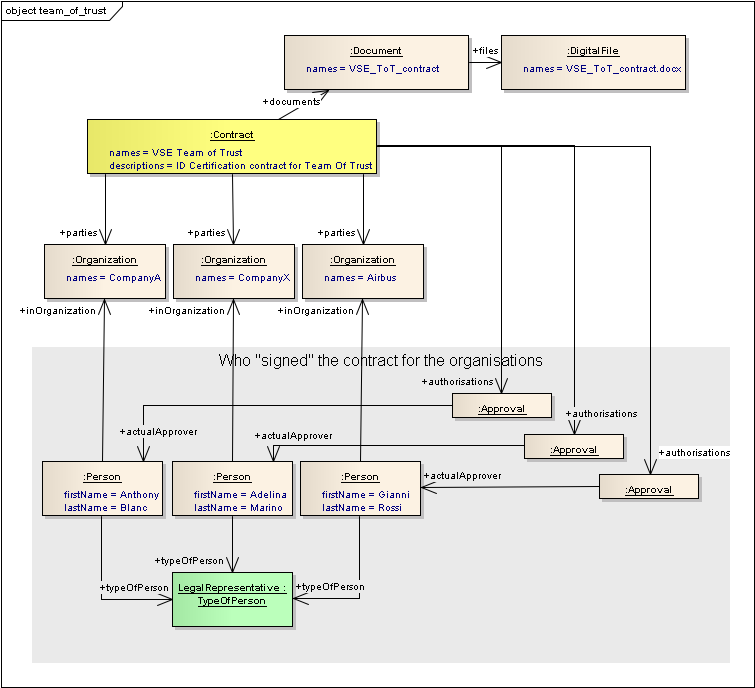
Contract for ID certification within a Team of Trust
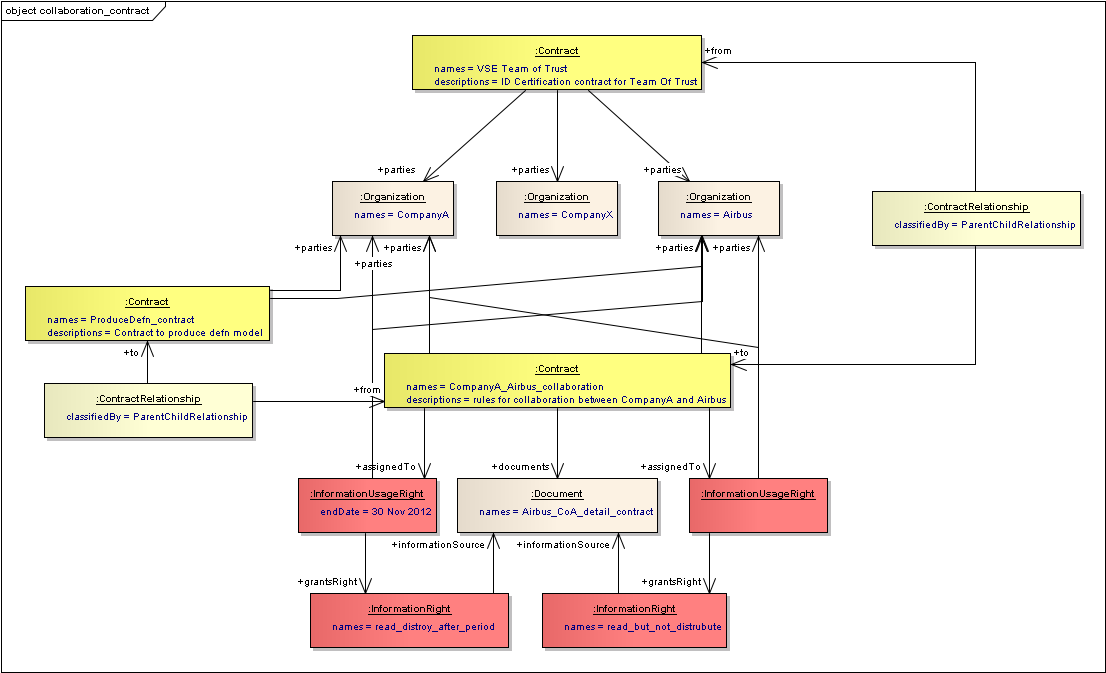
Contracts for the collaboration
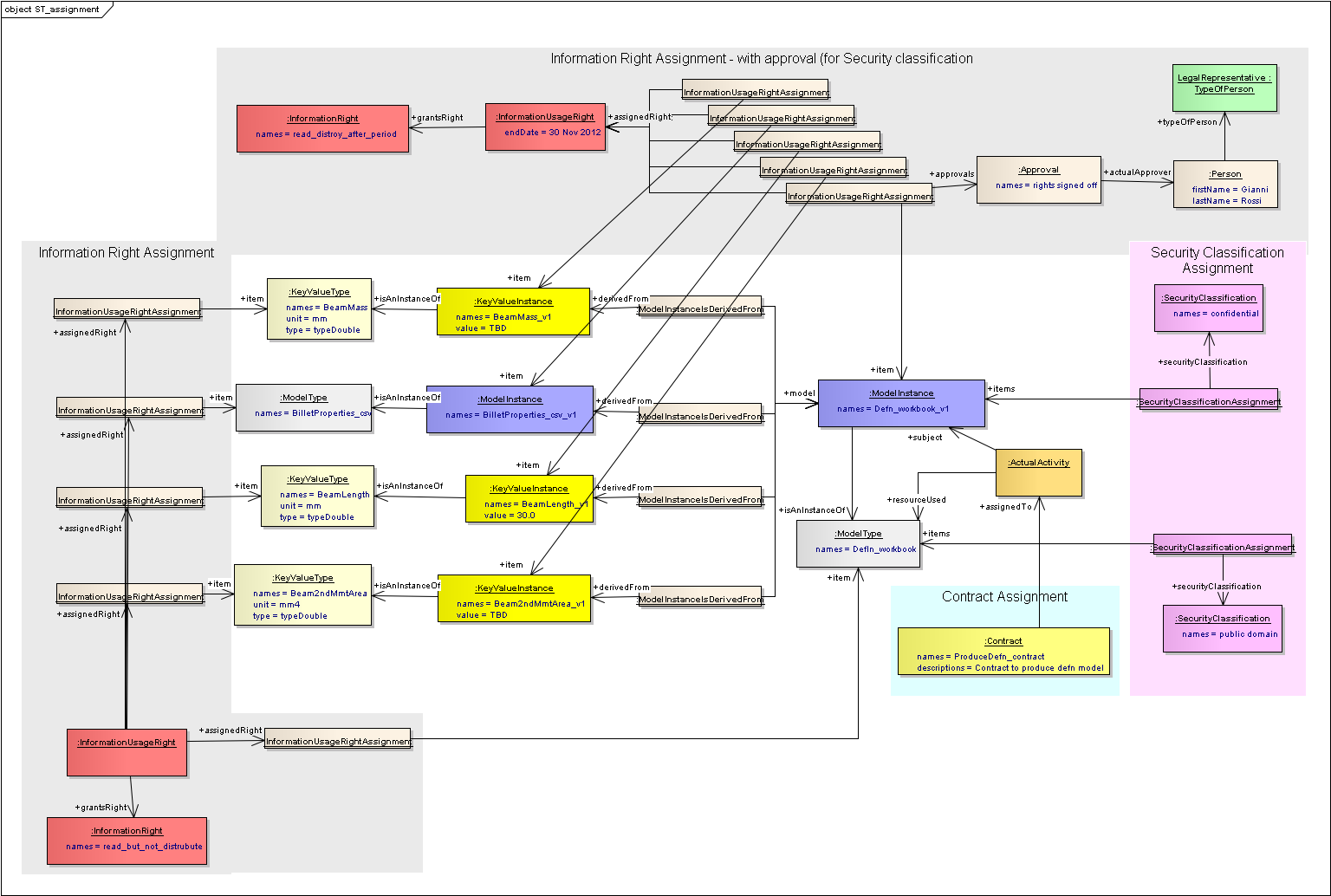
Assignment of Information Rights and Security Classifications
Value Modelling
See Value Modelling
- 1a. Stakeholder expectations are captured and validated
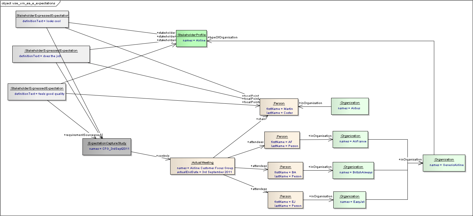
Expressed Expectations are captured using classes
- 1b. Stakeholder expectations are validated
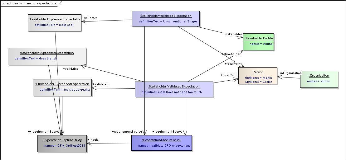
Expressed Expectations are Validated using classes
- Stakeholder needs identified, analysed
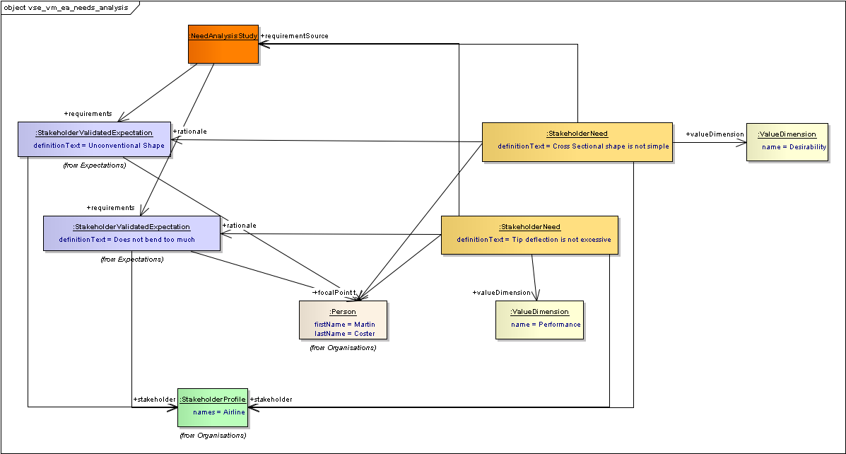
Stakeholder needs are identified
- Value Creation strategy for analysed and rank-weighted Needs
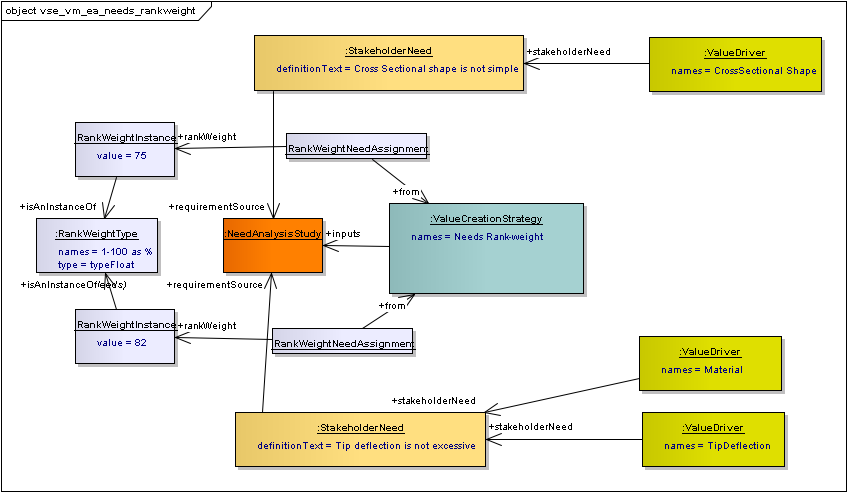
Stakeholder needs are rank-weighted in context with value drivers
- Quantified Objective Hierarchies with targets for analysed and rank-weighted Needs
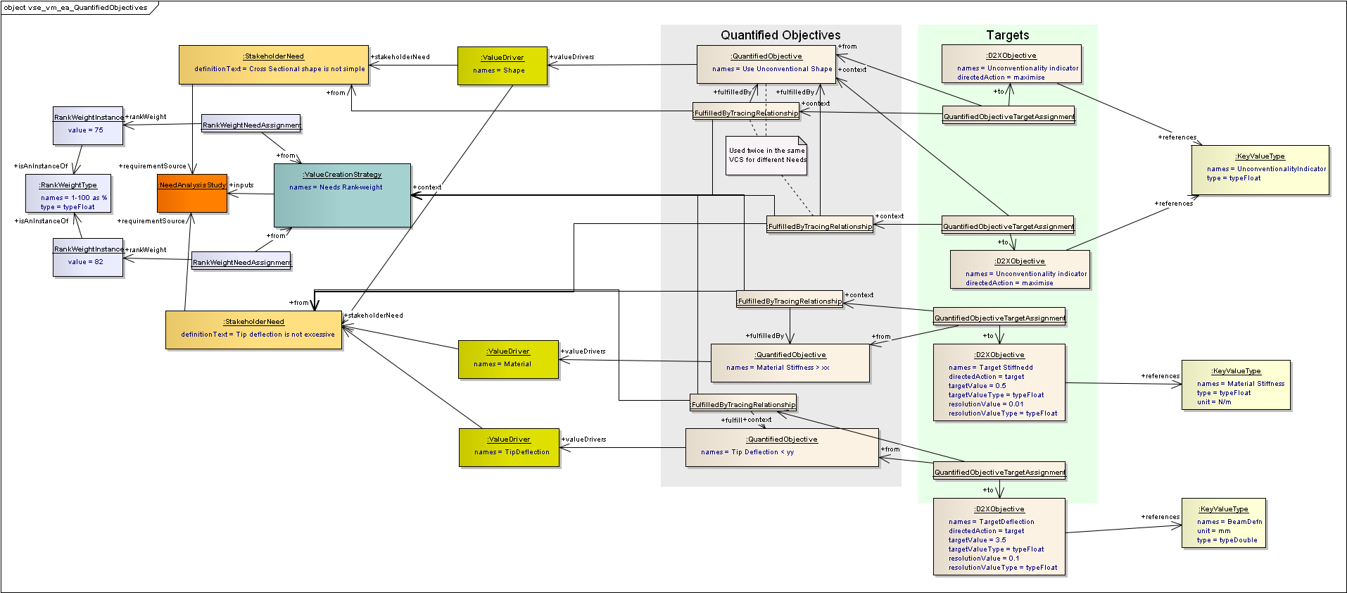
Quantified Objectives and Targets assigned to Needs and Value Drivers
- Value Creation strategy for analysed and rank-weighted Quantified Objectives
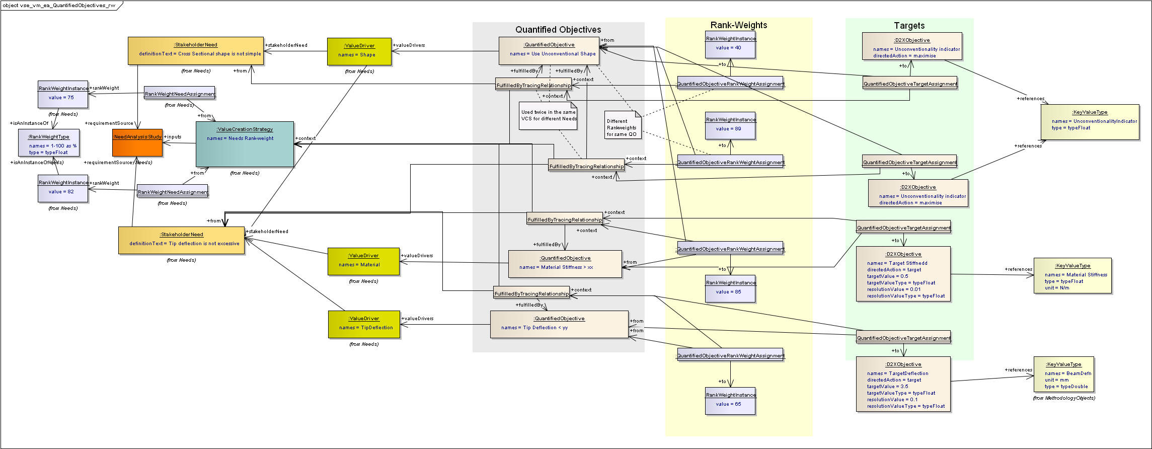
VCS with Rank-Weighted Needs fulfilled by Rank-Weighted Quantified Objectives with Targets
- Value Models developed
- Requirements established based on rank-weighted quantified objectives
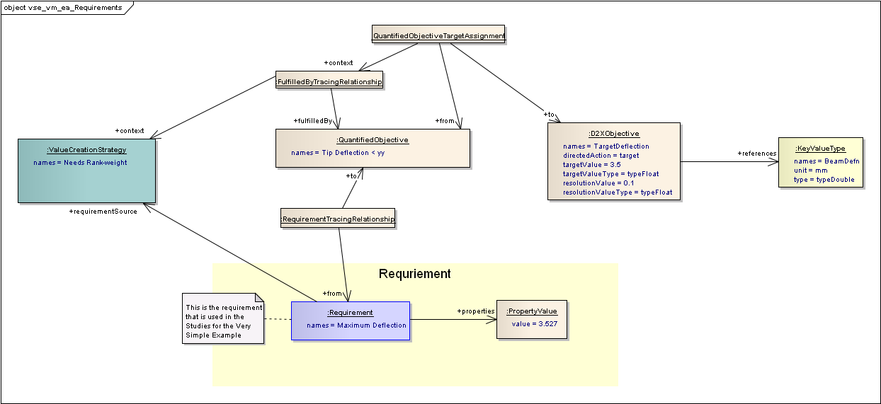
Requirements traced to Quantified Objective and Value Creation Strategy
Section author: Judith Crockford