Interfaces and Components
A page to explain how interfaces between components are handled, and how these relate to the other elements in the Business Object Model such as requirements, ModelTypes and ModelInstances.
Note
The icons representing Interfaces and Components, with the icons for the models are shown below. Interfaces are blue, with the connection represented as a bar with arrows pointing away. The ports are blue blocks on the yellow component.
Icons for Interfaces, Components and Models.
Overview
Introduction
It order to manage the development of a complex product like an aircraft, it is divided into logical pieces (or COMPONENTS) that can each be developed independently. The boundaries between the components are known as interfaces.
The components themselves can have many different representations, for example physical representations or behavioural representations.
For the purpose of this document, the view with the components and interfaces is known as the SYSTEM VIEW. The view with the representations is known as the PHYSICAL VIEW.
An interface is not an entity itself, but is made up of PORTs on components and CONNECTIONs between these ports. For example a complete system may have three components; a computer, an information network and a power supply. The computer can have a port for power that connects to a port on the power supply, and a port for data that connects to the information network. The components, ports and connections can all have multiple representations. Many connections can point to a single port, but each connection only points to two ports. For example a port on a wing can be connected to two alternative pylons, showing that the wing has alternative power plant configurations, but each connection points to the wing and one of the pylons.
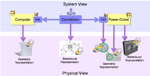
System View of Components, Connections and Ports, with representations in the Physical View
Interfaces can have hierarchies. For example the power interface between the computer and the power-supply can be broken down into electrical phases, or into assembly pieces of the cable etc.
Interface Connections and Ports can have type definitions and properties. They can also have Specifications applied, for example a connection may have a stiffness behaviour specification and a port may have specifications for mating conditions or positioning. On the computer example, the port on the power supply may reference IEC 60906-1 the International standard for 230V AC domestic plug.
Enterprise Architect Documentation
For more information see SysML - Interface Management Diagram
Computer - Power-Outlet Scenario
This scenario is purposefully not based on a CRESCENDO example so the engineering concerns do not cloud the issues, and so it is possible to concentrate on modelling the Interfaces and Components.
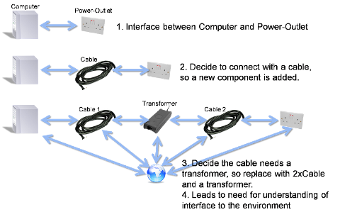
Overview of the Computer - Power-Outlet scenario
The scenario has the following evolutionary steps:
- Step 1. Interface between the Computer and the power outlet. At this stage how they are connected is undecided. E.g. it could be with a cable, or an induction loop.
- Step 2. A decision is made to resolve the interface with a cable
- Step 3. On investigation it is discovered that a simple cable is insufficient, and so the cable is replaced with cable-transformer-cable.
- Step 4. The transformer has specific requirements concerning the heat transfer, so an environment component is added and interfaced to all the other components.
The interfaces considered in the scenario are:
- Power - Electrical and Thermal
- Spacial - Movement of plug pins into socket
- Information - USB connection (used for the interface specification illustration)
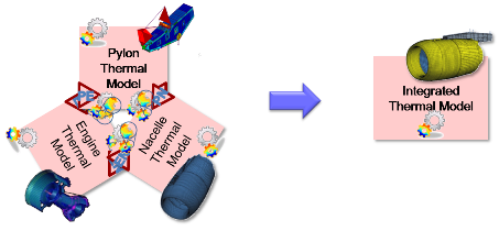
Wing - Pylon - Engine Scenario
The Wing - Pylon - Engine Scenario is a bigger picture view of the Engine - Pylon - Nacelle scenario used in the Power Plant Product Integration test case S3P1. The major part of the scenario will concentrate on the Engine - Pylon interface, but the Wing - Engine is added to reflect the similar levels used in the Computer - Power-Outlet Scenario described above.
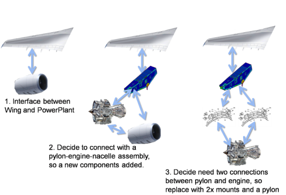
Overview of the Wing - Pylon - Engine example
The scenario has the following evolutionary steps:
- Step 1. Interface between the wing and the power plant. At this stage it is assumed that the number of power plants has been decided, and that they are to be slung under the wings. But not how they are to be attached to the wings.
- Step 2. A decision is made to attach the power plant using a pylon with engine and nacelle, but to be able to have different engines. Each engine can have a different pylon attachments, which means that there are unique pylons for each engine, but that each pylon must interface in the same way to the wing.
- Step 3. Concentrating on the Engine - Pylon interface for one engine type. It is decided that there will be two mounts, a forward and an aft mount. But it is not decided on the components that constitute each mount.
- Step 4. One of the mounts is further detailed with the mounting elements, ball and socket joints etc.
The interfaces considered in the scenario are:
- Power - Mechanical and Thermal
The scenario could be extended earlier in the lifecycle, to when it is undecided whether to have the engines mounted under the wings, or whether to have the engines embedded in the wings. For example with the concept plane shown below:

Concept Plane with unconventional engine attachment
More details for the Wing - Pylon - Engine Scenario
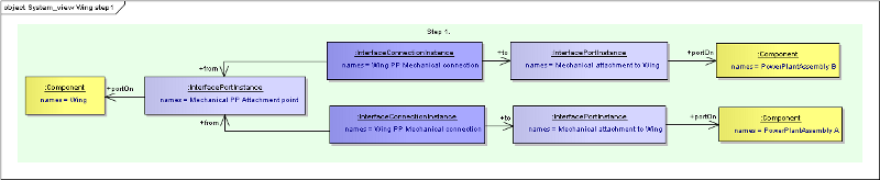
Step 1 in the scenario is when it is known that there are two types of power plant that are to be connected to the wing at the same place, but it has not been decided how to connect the power plant.
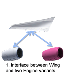
Wing to 2x PowerPlant interface
Seen as a representation using Business Object Model Classes:
In Step 2 of the scenario it has been decided to use a pylon as the attachment mechanism, so the power plant assembly is disassembled into Pylon, Engine and Nacelle.
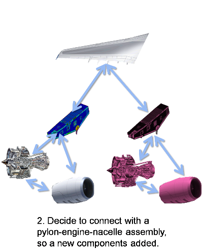
Wing to 2x PowerPlant interface
Seen as a representation using Business Object Model Classes, note most of the pylon-engine-nacelle interface elements are hidden, only the interface elements between Engine A and it’s pylon are shown, and these have already been identified as a forward and aft interface, though separate mount components have not been added at this stage.
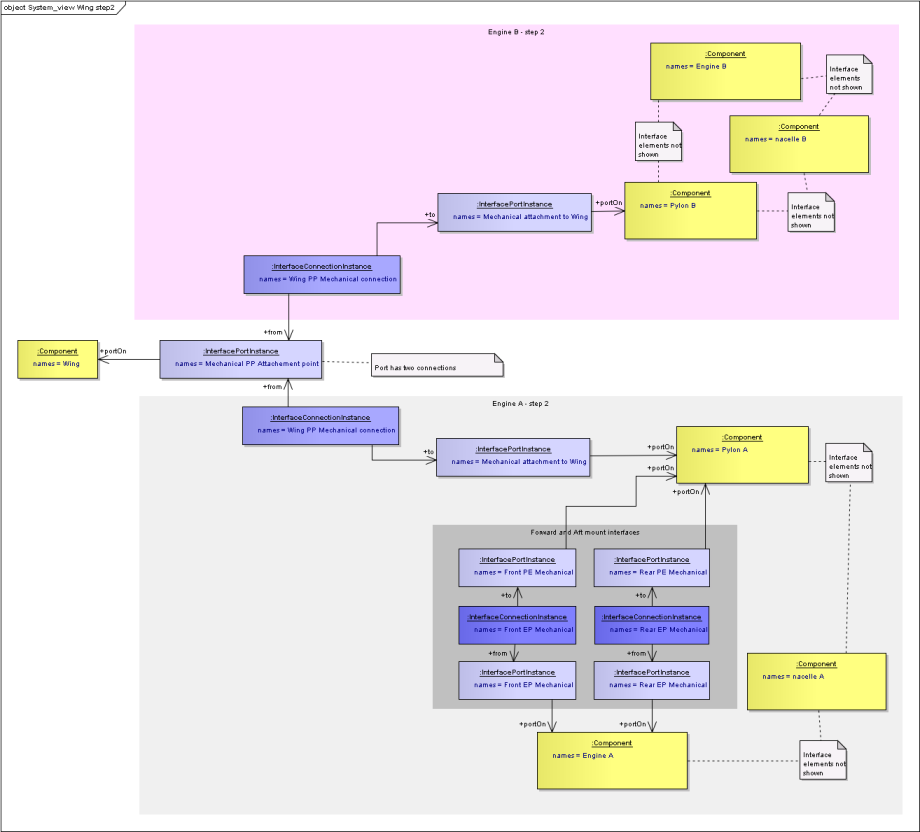
Step 2 using Business Object Model Classes
System View with Requirements
Requirements can be added to Components, Connection Instances and Port Instances. This is achieved by indicating that the requirement should be satisfied by the associated element. These requirements would then be verified by the representations of the element. See Requirements and Verification for more information, also the SysML - Requirement Verification Diagram.
Computer-PowerOutlet Example
Step 1, where the power transmission is not decided, a set of requirements can be attached to the elements in the system view as shown below.
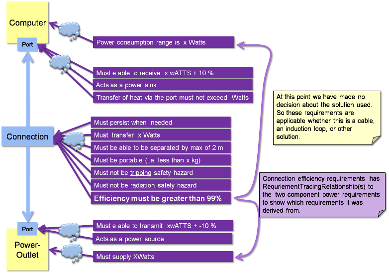
Computer - Power-Supply requirements
Computer Component: A requirement about the power consumption range that the computer must achieve
Power port on Computer: It should act as a sink, not a source, it must be able to transfer the minimum amount of power, and it must not get too hot
- Connection: It must transfer the power with a minimum efficiency, it must be persistent when it is needed, it must be portable, it has a maximum distance between the components that must be achieve, but no minimum distance etc.
- Port on the Power Supply: It should act as a source, and be able to transfer the minimum amount of power
- Power Supply component: It must supply the minimum mount of power
Some of these requirements are related to each other, for example the power transfer efficiency requirement on the connection is related to the consumption range on the computer and the minimum supply range on the PowerSupply. This is a tracing relationship and a RequirementTracingRelationship is used between the pairs of requirements.
Once a decision has been made to use a cable to connect the Computer to the Power Supply, the requirements can be assigned to the Cable, and also new requirements can added specific to the cable component, as illustrated below:
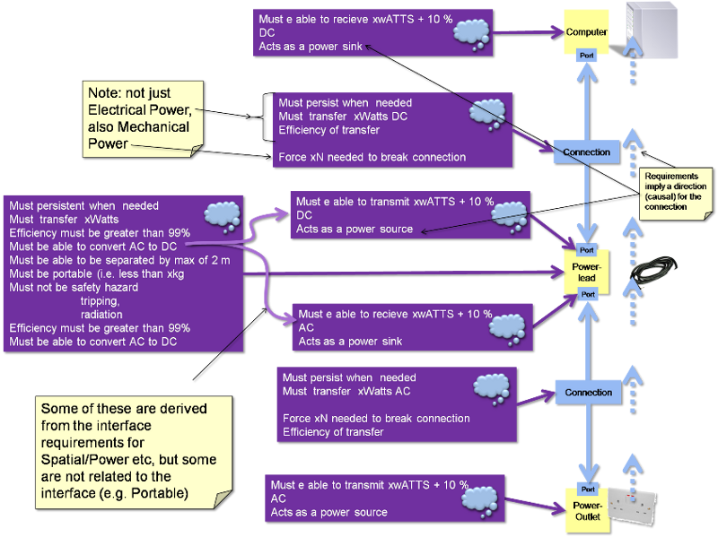
Computer - Cable - Power-Supply requirements
Things to note in the example are:
- Some requirements imply a direction (causal) to the Connection, where some ports have requirements to act as a sink, and others have requirements to act as a source.
- The connection between the power lead and the computer has two types of power requirements, electrical power (watts) and mechanical power (newtons).
- Some of the power lead component requirements are related from the interface requirements (e.g. must be able to convert AC to DC), but some are new to the component (e.g. must be portable).
Power Plant Integration - Product Integration Example
Step 1 in the scenario is when it is known that there are two types of power plant that are to be connected to the wing at the same place, but it has not been decided how to connect the power plant.
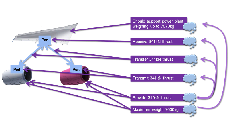
- Power Plant : Maximum weight, and required thrust requirements. These applied to both engines
- Wing : Must support the engine with a safety margin
- Connection : must transfer the trust from the engine to the wing with a safety margin
- Power Plant ports : must transmit the trust with a safety margin
- Wing port : must receive the trust with a safety margin
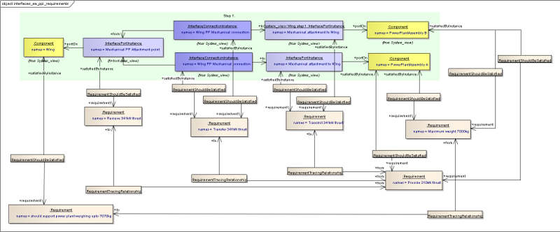
Step 1 requirements shown with Business Object classes
Hierarchies of System Views
As better understanding of the system is achieved, then more components are added, the interfaces are broken down into more detail and the so the hierarchies are configured.
Components can be related to other components using an “ComponentAssemblyUsage”. These are classes rather than simple relationships because they may need names and identifiers, and also links to other classes. In the case where there is a common component that is used in multiple places, the ComponentAssemblyUsage can be used in place of the Component in the System View, so can have Ports, and representations in its own right. An illustration is given below in the Engine - Mount-System - Pylon example. See also SysML - Breakdowns and Components Diagram. PortInstances and PortTypes are linked using a PortRelationship class. This is a class rather than a relationship so that different types of relationship can be defined without having to update the Business Object Model. This is achieved by using a string enumeration that is controlled outside of the Business Object Model.
Examples of type could be a Derivation relationship, or a Hierarchical Relationship.
- Derivation relationships are when the one port is derived from the other, for example when more detail is known about how an interface behaves because of design decisions. E.g. when it has been decided to connect the computer to the power-outlet with a cable the post-decision port on the computer is derived from the pre-decision port, in that it needs all the requirements/features that were understood from the pre-decision, but also some additional requirements/features.
- An example of a Hierarchical relationship could be on port that is for Thermal interface, and this has a hierarchical relationship to a Radiation-Thermal port, a Conduction-Thermal port and a Convection-Thermal port. i.e. the children of the hierarchy can be gathered up to make the parent. Similarly an Power port can be broken down into Mechanical power, Thermal power, etc. Ultimately a “world” port is made up of the Power, Information, Spacial and Matter constituents.
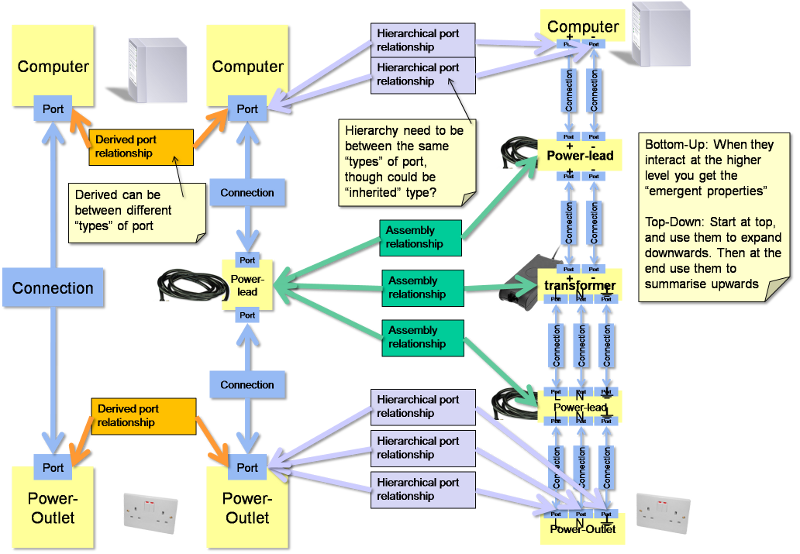
Computer-PowerOutlet Example
The following image shows several types of hierarchy:
- Port-Port Derived relationship (orange) : The “DC” port is derived from the “power sink” port.
- Port-Port Hierarchical relationship (pale blue) : The single DC watts port on the Computer is split into a positive port and a negative port. Similarly the AC Power supply port is split into live neutral and earth ports.
- Component-Component Assembly relationship (green): The power cable is made of an assembly of three components; an AC cable with (Live, Neutral and Earth ports), a DC cable (with positive and negative ports), and a transformer.
Power Plant Integration - Product Integration Example (Wing - Pylon/Engine/Nacelle)
This example shows the interface between the wing and “powerplant assembly” being expanded into the individual Pylon, Engine and Nacelle Components. The diagrams show how this is represented using the Business Object Model classes.
The following image shows two types of hierarchy:
- Port-Port Derived relationship (pale blue) :
- The port on the pylon that is connected to the wing is derived from the port on the PowerPlantAssembly that was connected to the wing
- The port on the wing that is connected to the pylon, is derived from the port on the wing that is connected to the PowerPlantAssembly
- Component-Component Assembly relationship (pale yellow): The PowerPlantAssembly is an assembly of three components; the Pylon, Engine and Nacelle. These three have their own interconnected set of interfaces most of which are hidden in the image for clarity.
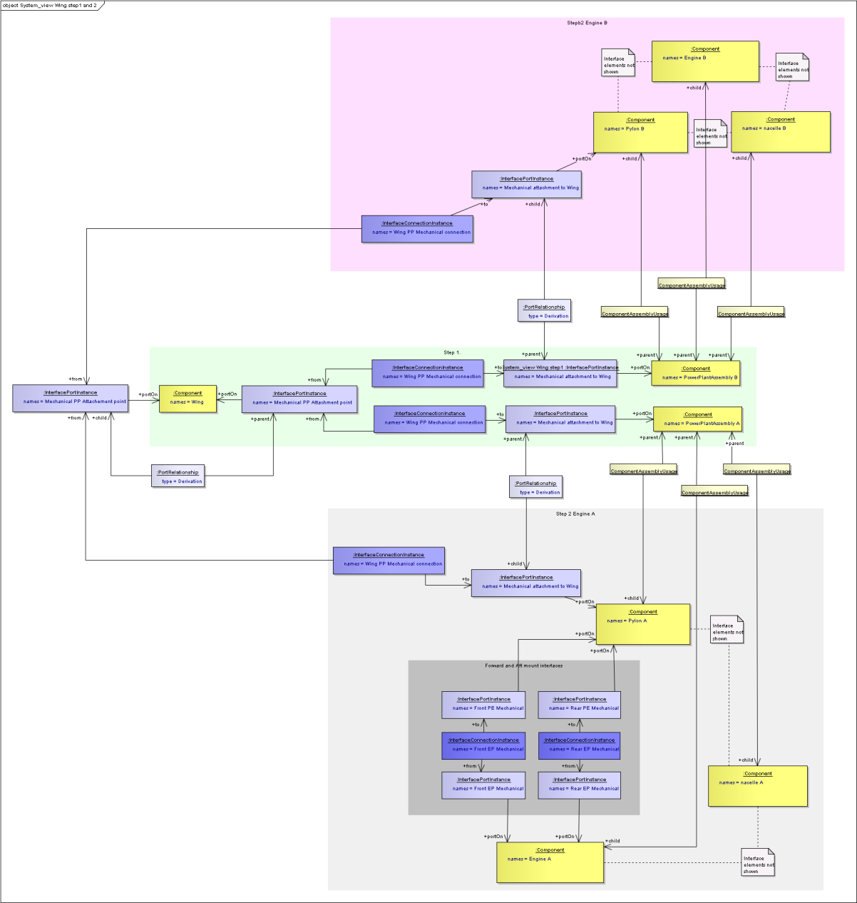
ComponentAssemblyUsage and Derived Port relationships using Business Object Model Classes
The following image shows hierarchical port relationships where the Thermal and Mechanical ports are children of the Energy port.
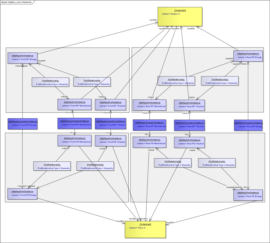
Hierarchical Port relationships using Business Object Model Classes
Power Plant Integration - Product Integration Example (Engine - Mount-System - Pylon)
This example is concerned with the interfaces between Engine, Mount-System, and Pylon. It assumes that initially it is not known how the Engine and Pylon are connected so a simple beam is assumed. This is then developed into a Mount-System, which is in turn developed into the individual components inside the Mount-System assembly.
- Step 1. A first interface is a simple Engine - Pylon interface.
- Ports on the Engine and Pylon Components with a Connection between
- The Connection has a representation in the Physical view of a beam
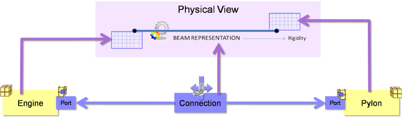
Engine - Pylon interface
- Step 2. This simple interfaces is further developed by including a Mount-System
- New Mount-System Component between the Engine and Pylon.
- Mount-System Component has a representation in the physical view - assumed to be a single model, but could have multiple representations if physical view is in many models.
- New Ports on the Engine and Pylon.
- Connect to ports on the Mount-System Component
- These have a derived relationship to the original port on the Component because they have some of the same behaviours, but also additional behaviours due to the change from a simple beam to a more complex representation.
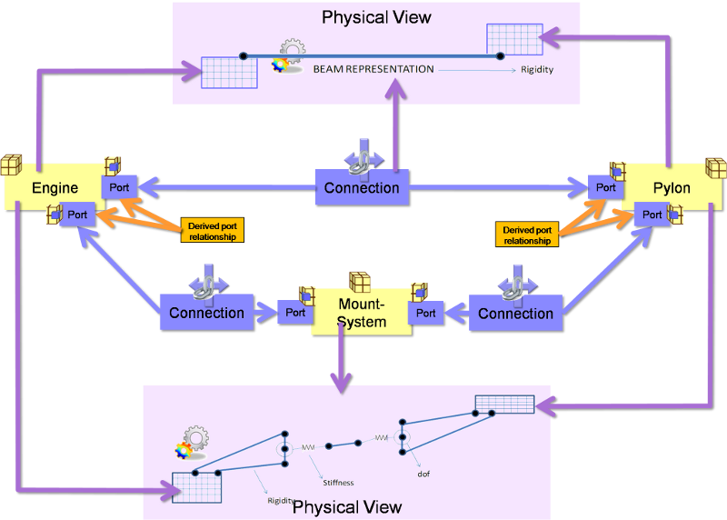
Engine - Pylon interface
- Step 3. Mount-System Component is expanded into the individual elements that make up the Mount-System assembly
- Assembly relationships between the Mount-System Component and the Components for the assembly
- The Mount system ports and the bolt ports have a “delegation” relationship between then to indicate that the specification for the Mount system port is delegated to the bolt port.
- If the Physical View is in many models, there can be representations to the different models, or if it is all in one model then they can each have a representation to the same model. In this way the specifications for each Component can be passed to the models.
- Some of the Connections also have representations as the Springs in the Physical view. These could themselves be individual models, or could be “AccessibleModelInstanceConstituents” (Publications) within the combined model
- The Connections to the Engine and Pylon Components use the same ports as in Step 2. This is because there is no change on the Engine and Pylon, and no additional information specified.
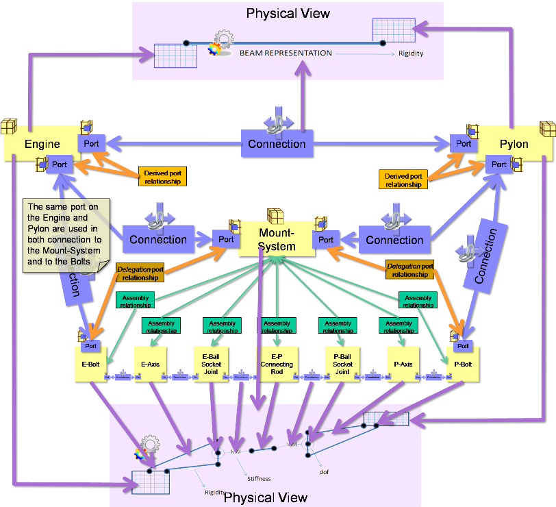
Engine, Mount-System, Pylon with Assembly and derived relationships
- Step 3 - alternative. If one component is used in multiple places and the connections are only applicable to one of those places, then the ports can be attached to the usage object (ComponentAssemblyUsage). The representation can also be associated to the usage rather (or as well as) to the Component itself. The diagram below shows the Connecting-Rod Component connected to two ComponentAssemblyUsage objects for the same Ball-Socket-Joint Component. This means that the Ball-Socket-Joint Component has to be able to cope with both scenarios. This is seen by Ball-Socket-Joint Component having two behaviour representations. Similarly there are two usages of the Axis and two or the bolt.
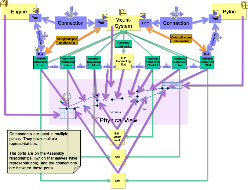
Use of Assembly ‘class’ (relationships) in the interface
Constructed and Unconstructed Interfaces
All the interfaces described above are “constructed” interfaces, i.e. ones that someone has constructed to split components. Unconstructed interfaces are ones that exist but have not been explicitly constructed, the most common of these are interfaces to the environment. In the Business Object Model there is no difference between these, but if it is needed to identify whether an interface is constructed or unconstructed, then the InterfaceConnectionInstance can be classified. See SysML - BaseObjects Diagram for more details on classification.
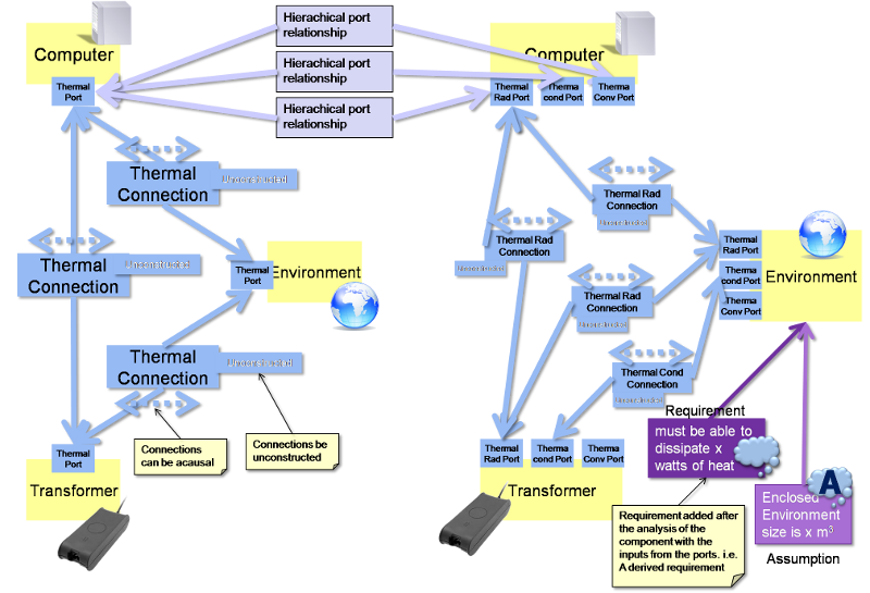
Computer-PowerOutlet Example
In the following example, the thermal interfaces between the Computer, the transformer and the environment have been added. When the transformer is embedded in the computer (e.g. in a desktop computer) then it’s heat output may impose requirements on an integral fan. When it is external (e.g. in a laptop computer) then there is no need for a fan, but it imposes requirement on the heat dissipation for the enclosed environment in which it is placed. Clearly the environment is infinite, so in order to make it a realistic interface some assumptions need to be made on the limits of the environment (e.g. minimum size of three cubic metres). In the case of the computer, these assumptions then translate into lines in an instruction manual.
Power Plant Integration - Product Integration Example
The following shows an interface between the engine and the environment, where the InterfaceConnectionInstance has been .classifiedBy and ExternalClass with a classReference of “UnConstructed”
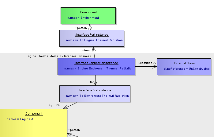
Unconstructed Connection between the Engine and Environment
Interface “Type” classes
Connections and Ports have Types and Instances - InterfaceConnectionType, InterfaceConnectionInstance, InterfacePortType, InterfacePortInstance. The purpose of a Type is to provide the definition for the Instances, for example a Bolted Flange Connection Type.
The Types:
- can include property definitions (e.g. Spring Stiffness constants Kx, Ky, Kz with unit of N), the instances should then provide the values for these properties.
- can inherit from other Types, so build up a conglomerate definition.
- are versioned
- can have documents to allow a more detailed definition than is possible with properties and descriptions.
- can have representations (in the physical view) of ModelTypes. The PortTypes can also have representations of AccesspbleModelTypeConstituents.
InterfaceConnectionTypes connect two InterfacePortTypes which are ports on BreakdownElements and Components. Note they cannot be ports on BreakdownElementUsage or on ComponentAssemblyUsage.
Interface Specifications
Instances and Types of Connections and Ports can have InterfaceSpecifications, and these specifications can inherit from other specifications. The specifications are versioned, and can have documents attached to define the specifications. A specification can be a standard, e.g. the specification for a USB connection. This is illustrated below.
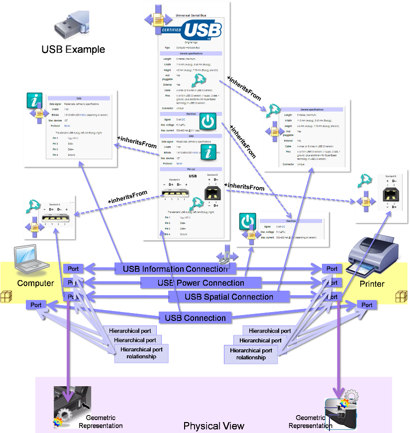
USB specification with inheritance.
The scenario shows the different areas of the interface that specify the Power, Information and Spatial details are contained in separate InterfaceSpecifications and overall USB specification inherits them. The Computer and Printer Components have three separate sets of ports and connections which are each concerned with only one area of interface. There is then an additional interface that is for the overall USB, and its ports have a hierarchical interface with the ports from the separate areas. The example shows the InterfaceSpecifications are inherited and then used by the overall interface. But it could be that the overall interface understands that it uses the specifications from the child ports in the hierarchy. Also included in the diagram are images of the geometrical representations for the ports on the Computer and Printer.
There is more than one way to declare the information to define an interface, this is because one way may be more suitable to another for a particular interface, and a combination is likely to be used as appropriate. The different ways are summarised as follows:
- InterfaceSpecification - with name, description, documents and inheritance. Can be attached to:
- InterfaceConnectionType
- InterfaceConnectionInstance
- InterfacePortType
- InterfacePortInstance
Properties - with the PropertDefinition on the Types (InterfaceConnectionType and InterfacePortType) and the Values on the Instances (InterfaceConnectionInstance and InterfacePortInstance)
Type documentation - formal and informal documentation describing the Connection or Port Type.
Power Plant Integration - Product Integration Example
The following example is for a mechanical interface between the Low Pressure Turbine Case, and the Tail Bearing Housing. It shows a ConnectionInstance with property values that define how the connection is to be modelled. The ConnectionType has the definitions for the properties, and the image shows the different options for the connections as the different choices are made for the properties.
The two ports point to the same InterfaceSpecification, and this contains details of the geometry and node locations for the interface. The node locations are provided either by a text document, or as a nastran representation.
The Physical View is also shown, with the Components having ModelInstance representations, and the ports having representations of AccessibleModelInstanceConstituents inside the ModelInstances. The Connection also has a ModelInstance representation.
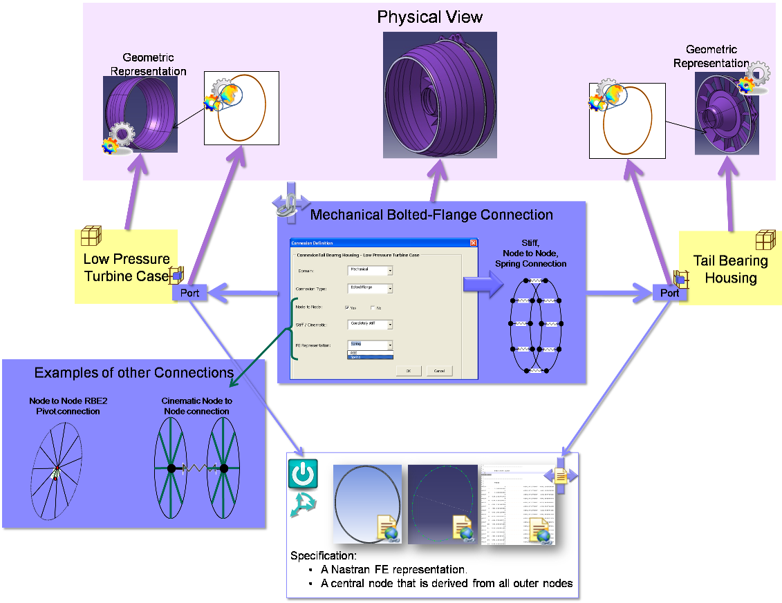
Components, Ports and Connections with specifications and representations.
The same scenario is illustrated below using classes from the Business Object Model. Note, this only shows the specifications and not the representations in the physical view.
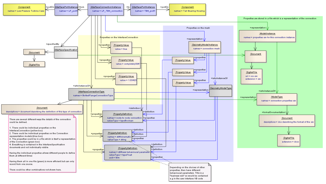
Specification possiblities using the Business Object Model Classes.
Linking the system view to the physical view, and assistance for Product Integration
The links between the system and physical views has been touched on earlier on this page. Each of the interface elements in the system view can have zero to many “representations” in the physical view. The class of representation allowed depends on the interface class as follows:
- InterfaceConnectionType : ModelType
- InterfacePortType : ModelType and/or AccessibleModelTypeConstituent
- InterfaceConnectionInstance : ModelInstance
- InterfacePortInstance : ModelInstance and/or AccessibleModelInstanceConstituent
- Component : ModelInstance
- ComponentAssemblyUsage : ModelInstance
When the representation relationships are initially set up, it is an indication of what data needs to be generated. For example, if a Mesh-ModelInstance is to be a representation of a Component, then the ModelType that the Instance isAnInstanceOf, has documentation containing the definition of the expected mesh characteristics.
The representations for ports can be used to indicate the type of boundary expected (e.g. a mesh, a node, a geometrical surface or curve etc.), and also used to indicate the interface boundary conditions. For example, a typical “Product Integration” problem has the following steps:
- Step 1. An integrated model is created which is made up of simplified models of the elements being integrated.
- Step 2. From this, boundary conditions are extracted for the interfaces between the elements.
- Step 3. Each element is then analysed separately using more complex models.
- Step 4. New simplified models are then created.
- Step 5. The simplified models are then integrated back together into a single model for the next iteration.
Because all the interfaces are contained in the integrated model, it is a representation of all the Connections. The boundary conditions can be exposed either using AccessibleModelInstanceConstituents, or by creating new models containing just the boundary conditions that are derived from the integrated model. These become the representations for the Ports. Using boundary conditions in separate models has the advantage that separate element analysis steps only need the model of the boundary conditions, not the complete integrated model from which to access the constituents. This is illustrated below:
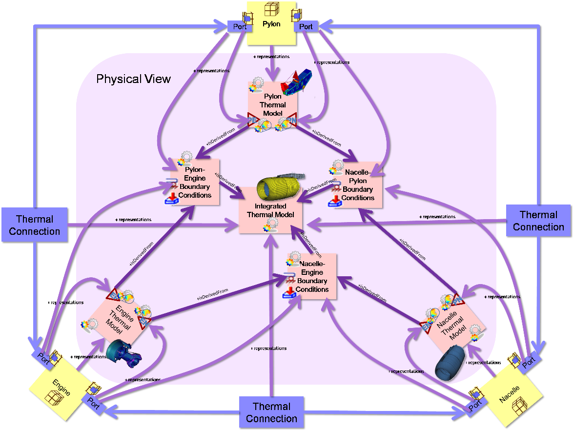
Representations of Interface elements in the Physical View
The above image also shows that the ports have representations which are AccessibleModelInstanceConstituents in the simplified models from step 4. This means that in the integrated model in Step 5. can join together the models in Step 4. using the “recipe” defined by the port representations and connections between ports. For example the port on the engine that is connected to the pylon has a representation of a accessible constituent (e.g. publication) inside the Engine model. This publication can be matched up to the accessible constituent (publication) inside the Pylon model that is a representation of the port on the pylon that is connected to the engine. The rules for how to match them up will be contained inside the specifications for the ports (and connections). This is illustrated below.
System to Physical view relationships to assist in Integration problem
At each iteration new instances of the models are created in the Physical view, and these are representations of the same Components, Ports and Connections in the system view. So the Components, Ports and Connections will end up with many model representations, but those models will have isEvolvedFrom relationships making it possible to view their lifecycle.
Power Plant Integration - Product Integration Example using Business Object Model Classes
The below diagrams show the same scenario but using the Business Object Model classes. The images are laid out in the same way as the schematic images above. The full example has both Front and Rear ports and connections, but only the front are shown for clarity.
The isDerivedFrom relationships (shown blue) are a simplification. A the Business Object Model uses a ModelInstanceIsDerivedFrom class with additional relationships to other classes. Including these makes the image too complex so they have been replaced with a simple relationship instead. For more information, see SysML - Associative Model Network
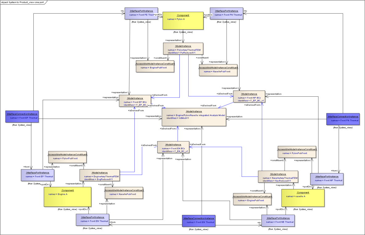
links between System and Product views for one iteration
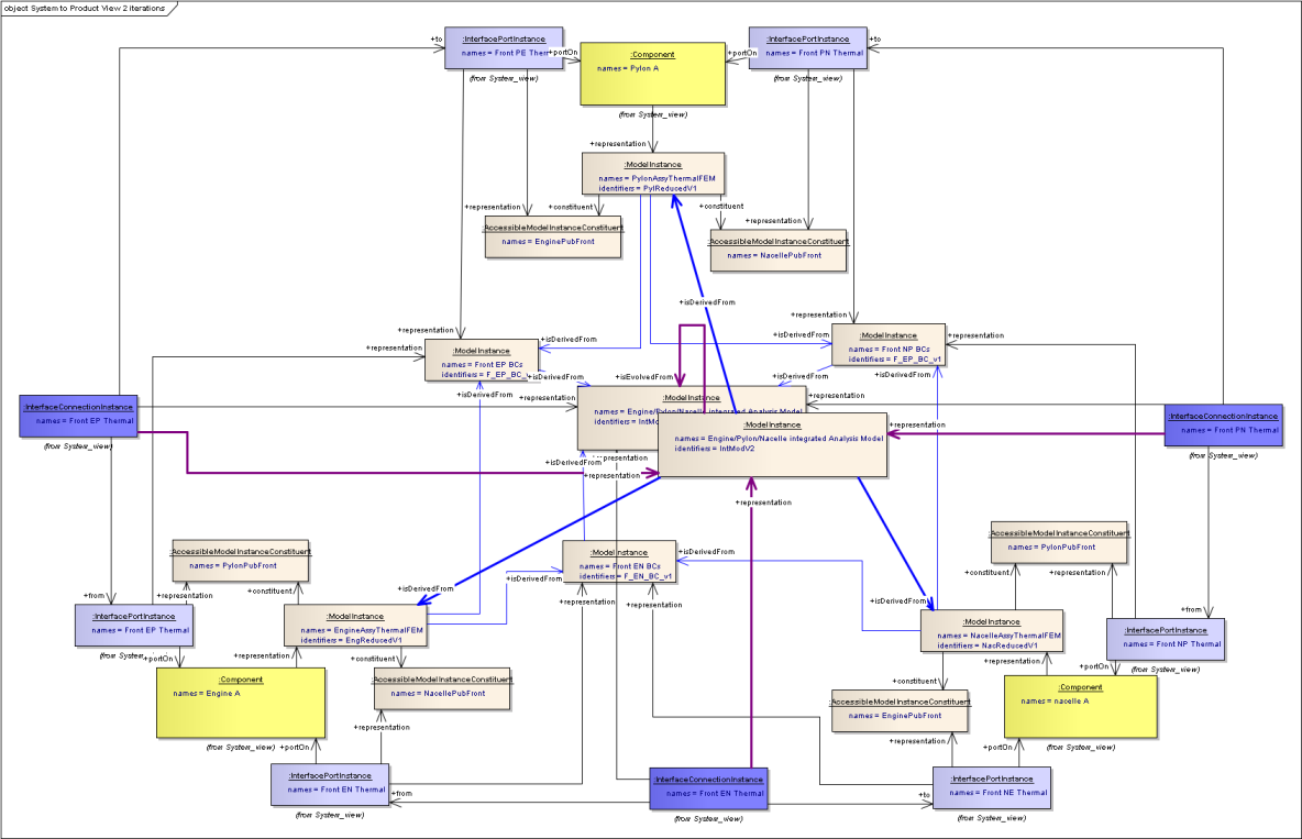
Adding Integrated model for second iteration - bold links
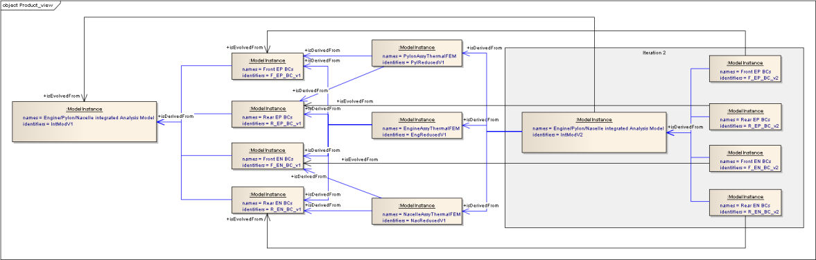
Product View subset: showing derived from and evolution relationships over two iterations
Section author: Judith Crockford